
Biophysical geoengineering compositions and methods

a biophysical geoengineering and composition technology, applied in special-purpose vessels, instruments, transportation and packaging, etc., to achieve the effects of enhancing nutrient supply, driving marine productivity, and superior performance of any biological system

Inactive Publication Date: 2013-09-17
LAMBERT KAL KAREL
View PDF5 Cites 4 Cited by
  • Summary
  • Abstract
  • Description
  • Claims
  • Application Information

AI Technical Summary

Benefits of technology

The present invention is about a new method for improving marine productivity and reducing global warming. It involves using a sustained-release composition with a combination of nutrients and minerals to stimulate biological growth and photosynthetic activity in the ocean. The composition also increases surface area for biochemical and photosynthetic activity and provides an instantaneous increase in the albedo of the ocean through a reflective surface. The invention is designed to be easily deployed on ocean surfaces and can be tailored for different ocean environments. It offers a long-term solution for sustainable ocean productivity and carbon sequestration.

Problems solved by technology

It is clear that prior art efforts at fertilization of the sea have focused on high bioavailability—unnecessarily.

Method used


Image

  • Biophysical geoengineering compositions and methods
  • Biophysical geoengineering compositions and methods
  • Biophysical geoengineering compositions and methods

Examples


example 1

[0151]A 30 mL aliquot of a 10% (w / v) stock of Miracle-Gro (Scott's Miracle-Gro Products, Marysville Ohio) was added to 50 mL of colloidal silica in methanol (Nissan Chemical America, Tarrytown N.J., CAS 112926-00-8) and the mixture was heated in an open vessel to reduce the volume to about 40 mL. A clear solution resulted. The solution was then allowed to cool and a clear hard gel matrix resulted. Over time in an open container, a somewhat brittle solid formed.

[0152]A binder such as a sol-gel precursor is optionally used to semi-permanently fuse the colloidal silica, as is done in silica “hardcoat”, a commercial process (see for example U.S. Pat. No. 6,587,263). Entrained air or CO2 is also incorporated in the matrix.

example 2

[0153]The following mineral components were crushed and mixed with a mortar and pestle.

[0154]

Major Inorganic SpeciesgmsIron Oxide50Iron Nitrate10Calcium Oxide20Calcium Phosphate10Zinc Carbonate5Magnesium Oxide4

[0155]To 10 gm of the above mixture, the following trace mineral components were added with further grinding.

[0156]

Trace Inorganic speciesgmsCopper Nitrate hemipentahydrate0.70Phosphomolybdic Acid0.20Manganese Chloride0.08Phosphomolybdic Acid0.01Cobalt Nitrate hexahydrate0.01Boric Acid0.005Selenium Chloride0.001Sodium Vanadate0.001

[0157]To this mixture of solids, 200 mL of colloidal silica in methanol was added. After heating with stirring to reduced volume and cooling, a hard gel formed. This gel when baked produces a rock-like composition without the decomposition indicative of organic charring.

example 3

[0158]As a first approximation, mix the aqueous suspension of Example 2 with 200 mL of colloidal silica in methanol as described above. After heating with stirring to reduced volume, add 300 gm of glass hollow microspheres and continue stirring until fully mixed. Charge 50 mL iron molds with the mixture, the molds having a selected shape and depth, with a shallow conical bottom profile. Bake to lithification.

[0159]During the early stages of baking, it is anticipated that the iron filings will sediment to the tip of the base of the mold and the glass hollow microspheres will rise to the surface of the liquid. This results in a “puck” shaped siliceous ingot on ejection from the mold. The ingot is comprised of highly dispersed inorganic minerals, sedimented iron filings, and a froth of microbubbles in a silicate matrix. In other words, puck density is here preferably non-uniform but is cumulatively less than that of water, that is to say the aggregate density is less than 1 gm / cm3. By ...


PUM


Abstract

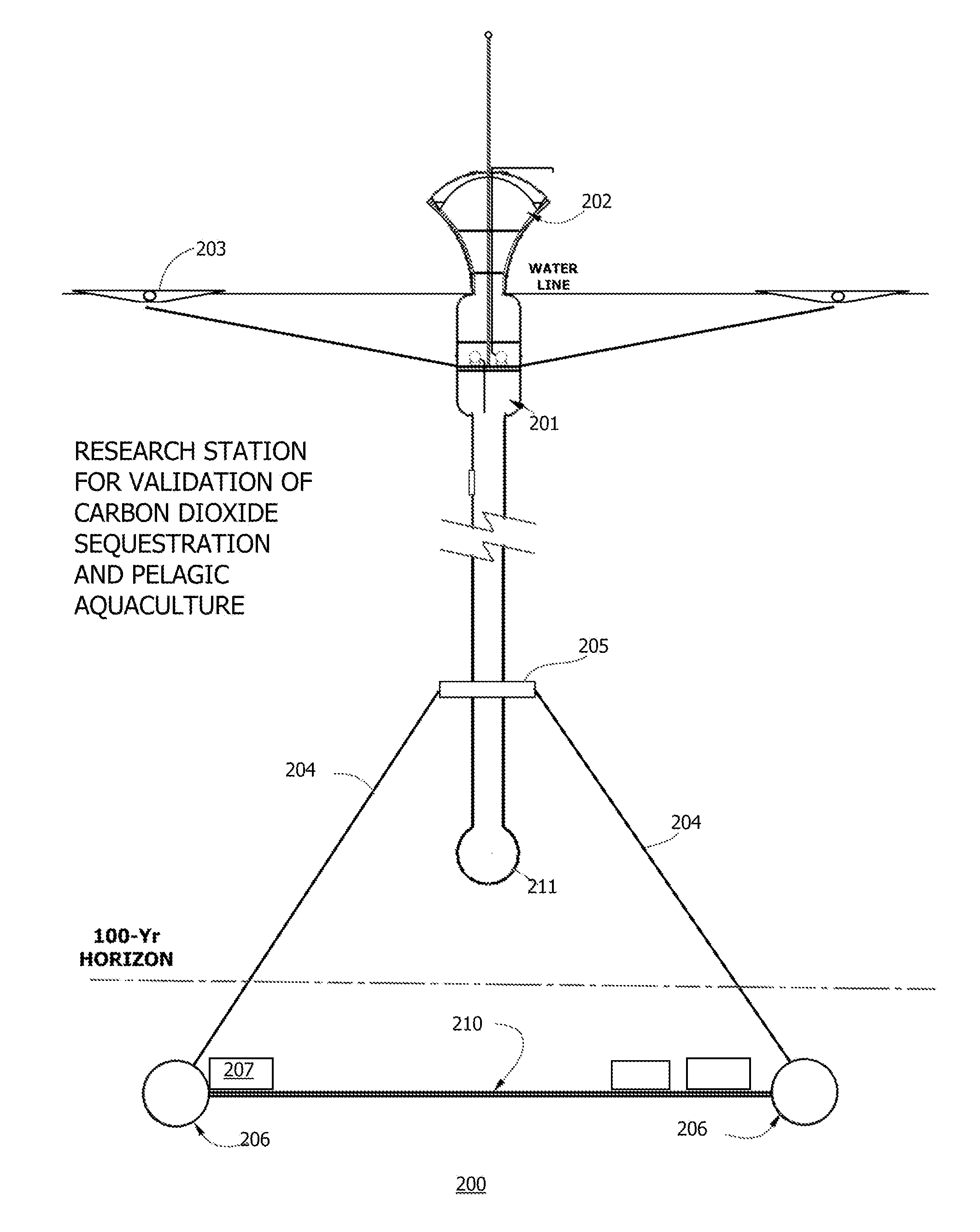
Described here are compositions, methods and apparatus for biological and physical geoengineering. Disclosed are inorganic particles, prill, pucks, or floats for dispersal on a body of water. These compositions are found to A) increase yields for pelagic aquaculture, B) increase carbon sequestration, and C) provide immediate relief from global warming by directly increasing surface albedo, reducing sea surface temperatures, and indirectly by increasing cloud nucleation activity. A vertical spar buoy or spar buoy network is provided. The buoys or array of buoys are designed to resist wave motion while supporting an analytical platform below the 100-Year Horizon. Sedimentary deadfall through the 100-Year Horizon is measured and flux of fixed carbon is reported and validated. Issuance of validated carbon sequestration certificates and monetization and trading of those certificates are also described.

Description

PRIORITY DOCUMENTS[0001]This application is a continuation-in-part, and claims the benefit of priority under 35 U.S.C. §120, of U.S. patent application Ser. No. 12 / 463,409 filed on May 10, 2009, now U.S. Pat. No. 8,033,879 issued Oct. 11, 2011, which is a continuation-in-part of U.S. patent Ser. No. 12 / 404,691 filed on Mar. 16, 2009, now abandoned, which is a Continuation-in-Part claiming benefit of priority under 35 U.S.C. §120 from U.S. patent application Ser. No. 12 / 345,661 filed Dec. 29, 2008, now abandoned, which is a non-provisional application claiming benefit of priority under 35 U.S.C. §119(e) from U.S. Provisional Patent Application Ser. No. 61 / 009,414, filed Dec. 29, 2007; all said priority documents are incorporated herein in entirety by reference.FIELD OF THE INVENTION[0002]The invention is an apparatus and method for engineering planetary temperature by remediating CO2 accumulation in the atmosphere to levels preceding the industrial revolution and by adjusting global ...

Claims


Application Information

Patent Timeline
Patent Type & Authority Patents(United States)
IPC IPC(8): B63B22/00B63B39/10
CPCA01G15/00B63B22/24B63B35/44C12N1/00G06Q40/00G06Q40/04
Inventor LAMBERT, KAL KAREL
Owner LAMBERT KAL KAREL
Learn More