Electrical feedthrough, in particular for medical implants

a technology of electrical insulation and medical implants, applied in the field of electrical insulation, can solve the problems of reflow soldering, affecting the electrical insulation capability of ceramics, affecting the electrical insulation capacity of circuit boards, etc., and achieves the effects of strong connection, high carrying capacity, and simple operation

Active Publication Date: 2013-09-17
BIOTRONIK SE & CO KG
View PDF9 Cites 24 Cited by
  • Summary
  • Abstract
  • Description
  • Claims
  • Application Information

AI Technical Summary

Benefits of technology

[0009]The present invention is based on the object of disclosing a hermetically sealed feedthrough for terminal electrodes made of a body-compatible material toward the implant outer side, which is contact-connectible in a manner having simple production on their inner end to the electronics situated there, in particular using reflow soldering.
[0011]The section of the terminal pin which can be joined at a lower energy and can preferably be soft soldered provides the advantage that the terminal pin can be joined in the interior of the implant securely and easily using lower energy—for example, lower heat energy up to 450° C., which is used above all in soft soldering processes. In particular, in a reflow process, cost-effective soft soldering can be produced simultaneously with other components on the electronic circuit board of the implant. These sections of the terminal pins may be installed together with the other components of the electrical feedthrough in the form of the at least one feedthrough bushing simultaneously in a common high-temperature soldering process, which in turn represents a particularly cost-effective mode of attachment. Furthermore, the formation of brittle phases between the section of the terminal pin and the soft solder used is avoided by use of the section of the terminal pin which can be joined at a lower energy in the interior of the implant, as otherwise formed, for example, between gold electrodes and soft solders having tin components.
[0012]Optionally, the sections of the terminal pin which can be joined at a lower energy may additionally also be provided with coatings which can be soft soldered particularly well, i.e., are easily wettable, having materials such as palladium (Pd), silver (Ag), copper (Cu), gold (Au), and alloys made of these materials, the coating having a layer thickness up to approximately 0.5 mm and a thickness up to approximately 200 μm in the case of a gold coating. A gold coating having this layer thickness is known not to form brittle phases together with soft soldering materials containing tin components.
[0014]The section made of the above listed materials, or other similar materials, which can be joined at a lower energy can be an attachment which is located on the inner end of the terminal pin. This attachment can be implemented as a pin, on the one hand, which is advantageously located in an extension of the longitudinal axis of the terminal pin and allows the ready accommodation of further components such as filters to ensure the electromagnetic compatibility (EMC filters) in the form of capacitors because of the lack of thickened areas. Alternatively, the attachment can also be implemented as a disk or round blank, which offers larger areas to the corresponding contact points on the partner circuit board as an advantage during the reflow process and allows mechanically stronger connections having higher carrying capacities.
[0015]The attachment which can be joined at a lower energy is preferably attached using a joint to the biocompatible section of the terminal pin, in particular hard solder alloys containing, for example, copper (Cu), silver (Ag), copper-nickel (CuNi), copper-zinc (CuZn), copper-tin (CuSn), silver-copper (AgCu), silver-copper-zinc (AgCuZn), silver-copper-zinc-tin (AgCuZnSn), silver-copper-tin (AgCuSn), silver-copper-zinc-cadmium (AgCuZnCd), copper-phosphorus (CuP), copper-phosphorus-silver (CuPAg), or copper-gold (CuAu), using which temperature inhomogeneities during the brazing process may be compensated for. Brazing using gold solder / gold solder alloys is preferred. Further, alloys thereof having additional possible alloy additives such as Pb, Sb, As, Bi, P, N, Be, Ni are also possible. Furthermore, the attachment which can be joined at a lower energy can be soldered, welded, crimped, clamped, or glued in an electrically conductive manner on the biocompatible section of the terminal pin using a joint, but is preferably brazed using gold solder. Preferably, the joint between the biocompatible section and the attachment which can be joined at a lower energy is located inside the implant housing in relation to the connection solder. This is the preferred type of attachment, because it is simple, reliable because of a lack of brittle phases, has mechanical carrying capacity, and can be implemented simultaneously together with the further feedthrough components in the same soldering process of the feedthrough. Because this attachment occurs already before the attachment to the electrical circuit in the interior of the implant, a welding or brazing procedure can be performed therein at the joint. In a preferred embodiment, the joint can be located within the at least one feedthrough bushing. It may thus be implemented easily in the soldering process of the feedthrough because of the centering action of the feedthrough bushing and may additionally protect it from mechanical strains and further influences. Furthermore, it is particularly preferably possible to also enclose it in the glass solder. This results in more extensive protection from mechanical strains, because the joint and the adjoining pin areas are mechanically decoupled toward the exterior by the glass solder.

Problems solved by technology

Above all in the case of terminal pins made of niobium, tantalum, or titanium, the problem exists that only welding methods come into consideration in order to produce a connection to other conductors, for example, to the terminal lines or to device electronics attached to the circuit in the interior of the implant, for the production of secure, low-resistance, mechanically stable, and long-lived electrical contacts to the described biocompatible terminal pins.
The required high temperatures of the welding procedure may generate metal vapors and / or welding sprays, however, which impair the electrical insulation capability of the ceramics and / or damage the circuit boards and therefore frequently require additional protective measures.
Due to these properties, reflow soldering, which is well known in the electronics sector, has simple production technology, and is efficient, is also not possible or is not readily usable with such a terminal pin.
In the case of the described ceramic feedthroughs having platinum / iridium terminal pins, it is known that without special protective precautions, they display problems with the detachment of the metal coating of the feedthrough bushings upon the soldering using gold solder and have poor wettability of the platinum / iridium surfaces with soft solder.
As a result, the noted reflow soldering is generally unreliable.
Fundamentally, the coating of the pin surfaces in the case of niobium, tantalum, or titanium terminal pins on the inner side for easy wettability with soft solder for the attachment to the internal electronics is either not possible at all or is only possible with increased effort, in that metal coatings which can be soft soldered are applied using welding technology or plasma-physical pathways, for example.
This design is too complex for feedthroughs having simple terminal electrodes, and efficient manufacturing would not be possible in the case of a corresponding layout of the feedthrough.

Method used


Image

  • Electrical feedthrough, in particular for medical implants
  • Electrical feedthrough, in particular for medical implants
  • Electrical feedthrough, in particular for medical implants

Examples


Embodiment Construction

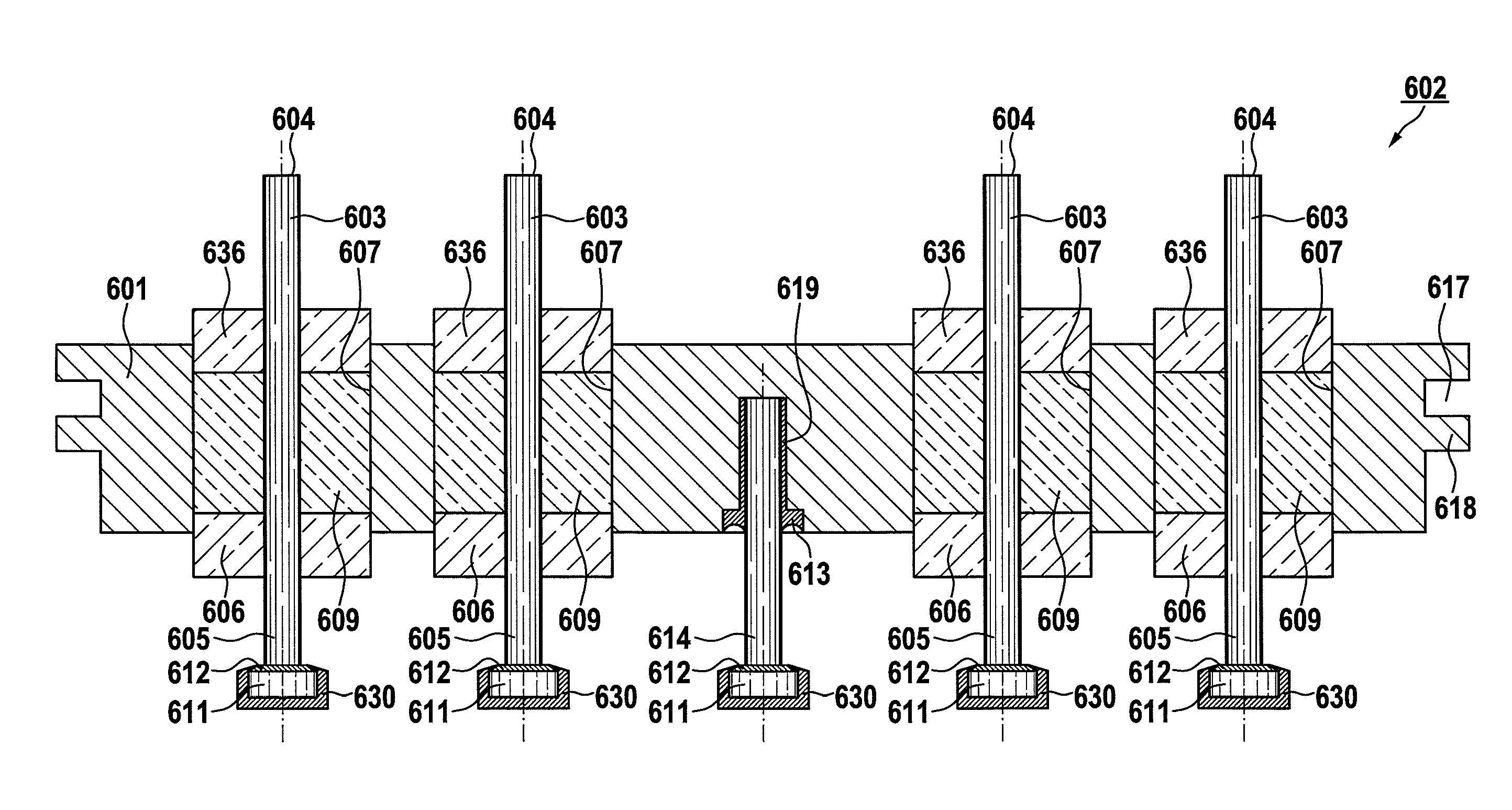
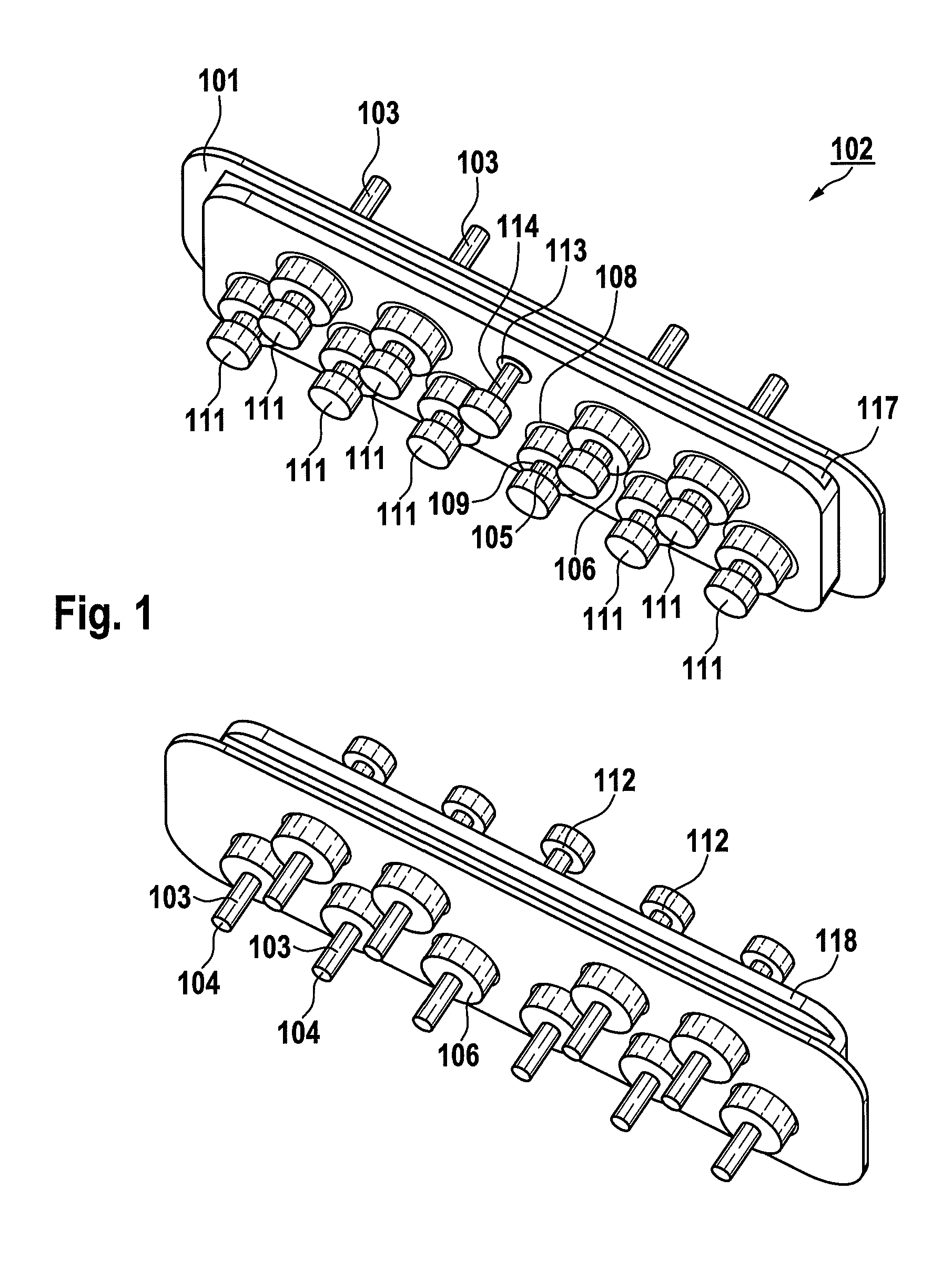
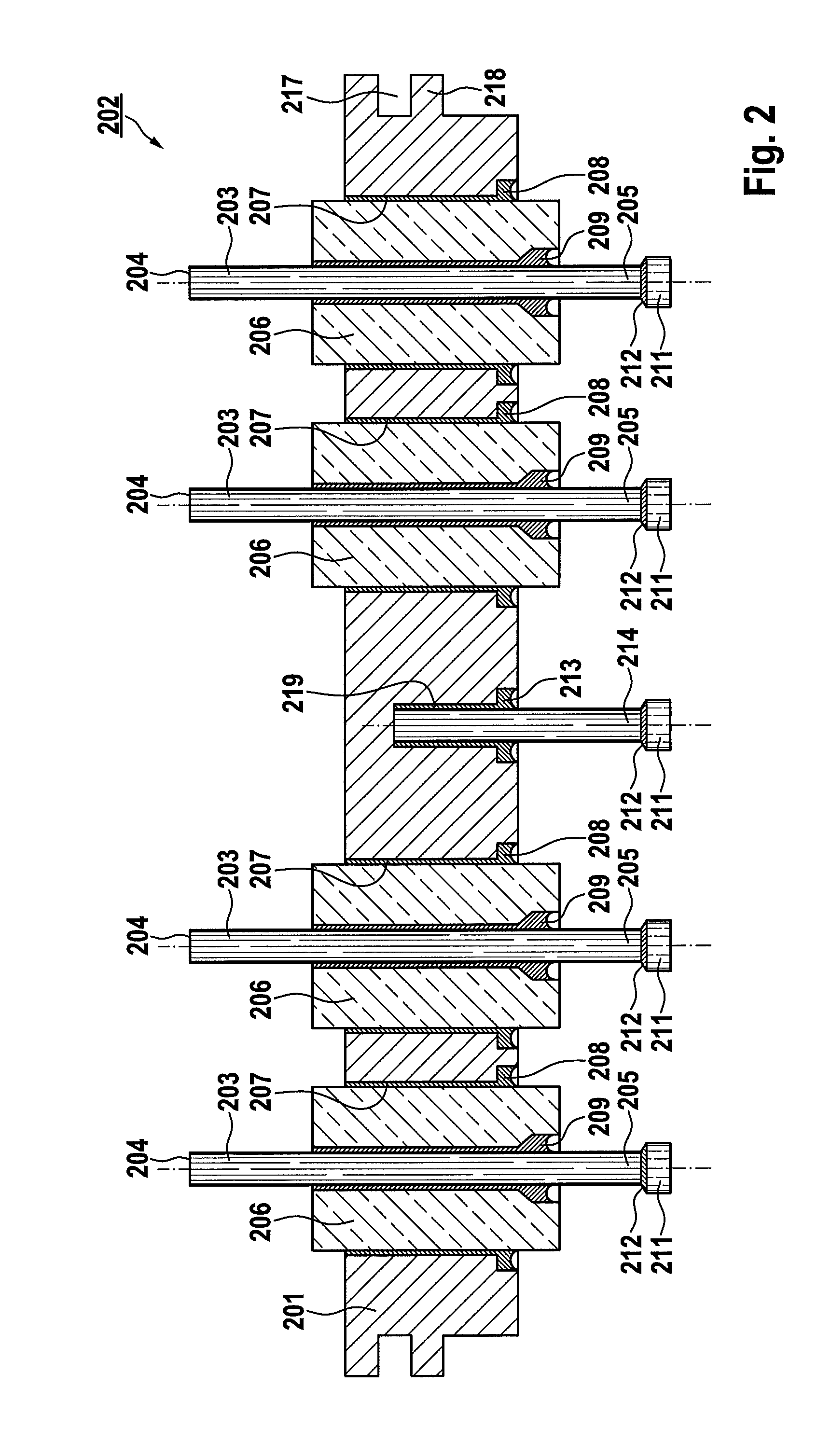
[0028]FIG. 1 generally shows an electrical feedthrough in a spatial illustration of a fundamental construction of a series feedthrough 102 having a view of the inner side (protruding into the implant interior) and the outer side. The electrical feedthrough includes a flange 101, which preferably consists of, but is not limited to, Ti, Nb, Ta, Zr, alloys made of one or more of the elements, or further additive elements such as, but not limited to, Hf, Al, Fe, P, Si, Mn, or C, or ceramic, in which multiple feedthrough bushings 106 are located, to which terminal pins 103 are connected by soldered connections. An attachment 111, which can be soft soldered, of the terminal pin 103 in the form of a disk can be recognized on the inner view, which is electrically and mechanically attached to the terminal pin 103 by a joint 112. The components identified therein are described further in FIG. 2. The feedthrough is constructed in this and the following figures as a series feedthrough having a ...


PUM


Abstract

An electrical feedthrough, in particular for use in an electro-medical implant, having a flange enclosing at least one feedthrough bushing and at least one terminal pin enclosed by the at least one feedthrough bushing, the terminal pin having at least one section which can be joined at a lower energy in the interior of the implant.

Description

RELATED APPLICATION[0001]This patent application claims the benefit of U.S. Provisional Patent Application No. 61 / 318,405, filed on Mar. 29, 2010, which is hereby incorporated by reference in its entirety.FIELD OF THE INVENTION[0002]The present invention relates to an electrical feedthrough, suitable, in particular, for electromedical implants, such as, but not limited to, implantable cardiac pacemakers, defibrillators, cardioverters, nerve and cerebral stimulators, hearing aids, implantable medication pumps, and / or other electrically active implants, which include a hermetically sealed housing, and batteries having a hermetically sealed housing for these electronic implants.BACKGROUND OF THE INVENTION[0003]Such feedthroughs typically have a flange, through use of which they are inserted into a housing wall of the electro-medical implant, preferably by a thermal joining method such as welding or soldering. An apparatus having, inter alia, a circuit board which is capable of processi...

Claims


Application Information

Patent Timeline
Patent Type & Authority Patents(United States)
IPC IPC(8): H02G3/08
CPCA61N1/3754
Inventor TESKE, JOSEF
Owner BIOTRONIK SE & CO KG
Why Eureka
Try Eureka