Control device for vehicle electric drive motor and vehicle with the same

a technology of electric drive motor and control device, which is applied in the direction of electric propulsion mounting, dynamo-electric converter control, battery/fuel cell control arrangement, etc. it can solve the problems of inapplicability of the cold start operation of the battery, the difficulty of using only the d, and the inability to perform both the vehicle driving mode and the battery warm-up mode by using the electric motor at the same time. , to achieve the effect of reducing the battery temperature and speeding up

Active Publication Date: 2013-09-17
HITACHI LTD
View PDF7 Cites 12 Cited by
  • Summary
  • Abstract
  • Description
  • Claims
  • Application Information

AI Technical Summary

Benefits of technology

[0014]According to the present invention, for example in a case of that the vehicle to be controlled is an electric vehicle, and in a situation where the battery warm-up is required for a cold start of the vehicle, the q-axis current value for vector control that is required for vehicle running (based on the required drive torque of the motor) is set while the d-axis current value is set so as to increase with a decrease in the battery temperature. Therefore, the battery warm-up can be speeded up no matter whether the electric vehicle is stopped or running. On the other hand, when the present invention is applied to a hybrid vehicle, the vehicle can run by using the electric drive motor instead of the internal combustion engine no matter whether a battery warm-up mode is selected, and permits the above-described battery warm-up. Thus, the present invention makes it possible to provide a motor control device and a vehicle that properly take the environmental considerations into account no matter whether an electric vehicle or a hybrid vehicle is to be controlled.

Problems solved by technology

Meanwhile, the battery warm-up operation (cold start operation) described in Patent Document 1 is not applicable for so-called electric vehicles which uses only an electric drive motor as a vehicle drive source.
More in detail, if adopting the technology of Patent Document 1 to the electric vehicle, only the d-axis current for vector control is since fed through the electric drive motor during a cold start operation (in a situation where battery warm-up is required), it is difficult to perform both the vehicle driving mode and the battery warm-up mode by using the electric motor at the same time.
Namely, if adopting the technology of Patent Document 1 to the electric vehicle, the battery warm-up technology is applicable to a situation where the vehicle is stopped, but, in a driving mode (in a mode in which a required drive torque for the motor is generated through an accelerator) at a vehicle cold start, required is since a q-axis current (torque component current), it is difficult to make a situation of using only the d-axis current for the battery warm-up operation.
Consequently, from the view-point of environmental considerations such as emissions reduction, the hybrid vehicle does not make full use of its abilities.

Method used


Image

  • Control device for vehicle electric drive motor and vehicle with the same
  • Control device for vehicle electric drive motor and vehicle with the same
  • Control device for vehicle electric drive motor and vehicle with the same

Examples


first embodiment

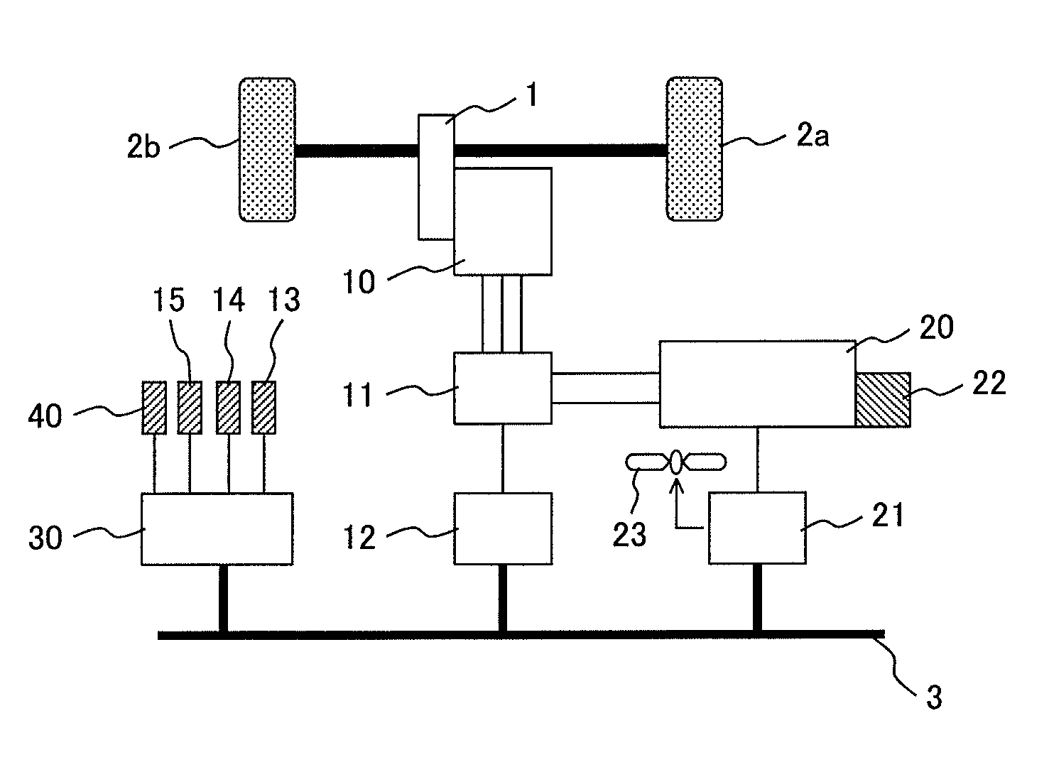
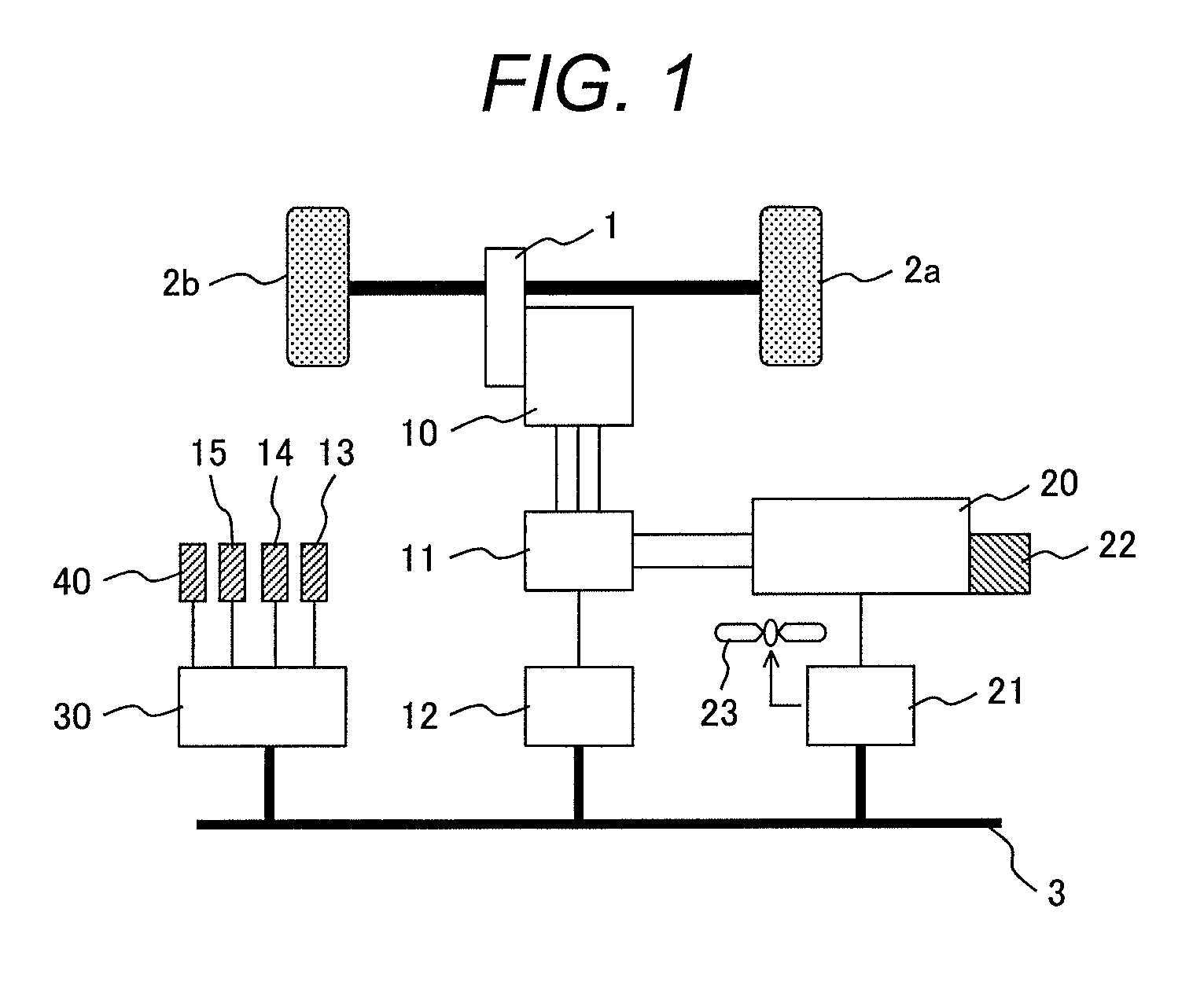
[0023]FIG. 1 is a schematic diagram illustrating a vehicle with a motor control device according to a first embodiment of the present invention. As an example, an electric vehicle having a vehicle electric drive motor 10 as a drive source is shown in this schematic diagram.

[0024]The vehicle according to the first embodiment shown in FIG. 1 includes three ECUs (electronic control units): a battery ECU 21, a motor ECU (motor control device) 12 for controlling the drive motor 10, and a vehicle ECU 30 for providing overall control of the vehicle. The battery ECU 21 calculates a state of charge (SOC) based on a voltage across a battery 20 to be a vehicle power source, a charge-discharge current, and an integrated charge-discharge current, and acquires a battery temperature sensed by a battery temperature sensor 22. Thereby, the battery ECU 21 manages the charge-discharge current and other properties of the battery 20. Further, the battery ECU 21 outputs the SOC and other information abou...

second embodiment

[0051]FIG. 6 is a schematic diagram illustrating a vehicle with the motor control device according to a second embodiment of the present invention. The second embodiment achieves the battery warm-up by using not only the heat derived from the battery's self-heating based on the d-axis and q-axis currents but also the heat generated by the drive motor and inverter.

[0052]In the configuration shown in FIG. 6, elements designated by the same reference numerals as those in FIG. 1 have the same functions as the corresponding elements shown in FIG. 1 and will not be redundantly described. In the second embodiment, the vehicle shown in FIG. 1 includes the battery ECU 21, the motor ECU 12, and the vehicle ECU 30, which are the same as the corresponding elements used in the first embodiment.

[0053]The present embodiment warms up the battery 20 not only by using the heat derived from the battery's self-heating based on the d-axis and q-axis currents as is the case with the first embodiment, but...

third embodiment

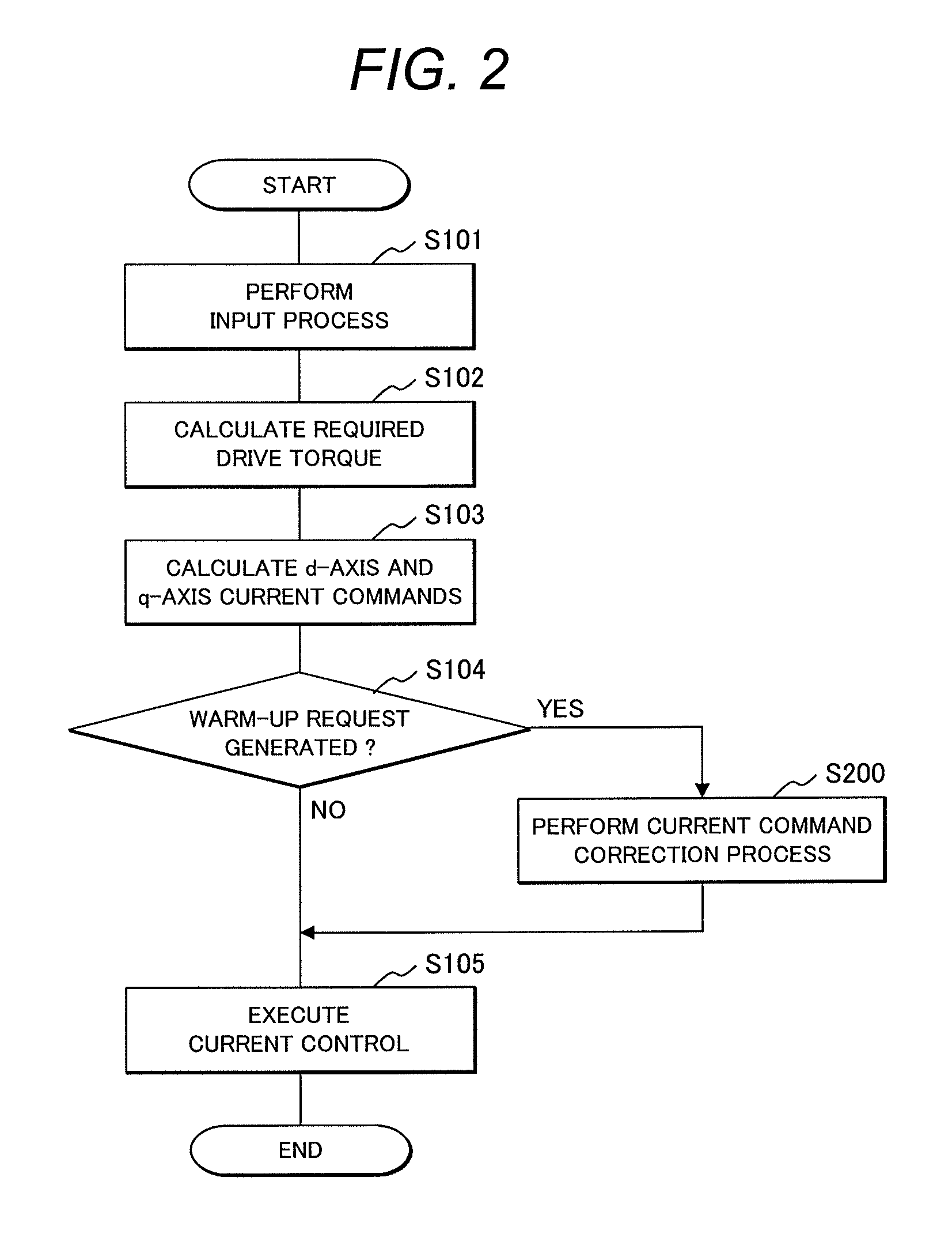
[0067]FIG. 7 is a flowchart illustrating motor current control executed during a battery warm-up operation for a vehicle applied to a third embodiment of the present invention.

[0068]The vehicle according to the third embodiment has the same configuration as the vehicle according to the first embodiment. As is the case with the first embodiment, the third embodiment executes d-axis current control and q-axis current control during a battery warm-up operation in accordance with the battery temperature and the required drive torque signal. However, the third embodiment differs from the first embodiment in that, while the vehicle is stopped, the motor ECU 12 executes a battery warm-up operation by using the d-axis current without reducing the q-axis current to zero so as to set the q-axis current value corresponding to a drive torque for allowing the vehicle to creep operation with assumption that the brake is released.

[0069]The above-mentioned motor control will now be described with r...


PUM


Abstract

A controller for vector-controlled motor of vehicle judges whether a battery needs to be warmed up in accordance with an output of a battery temperature sensor, and when the battery needs to be warmed up, in situation (i) where the vehicle is stopped, sets a q-axis current value of the motor at zero, or when a brake is released from the situation (i), sets a q-axis current at a value corresponding to a drive torque for a vehicle creep operation, and sets a d-axis current at a value for battery warm-up. When the battery needs to be warmed up in situation (ii) where the vehicle is running, the controller sets a q-axis current at a value corresponding to a drive torque of vehicle running and sets a d-axis current at a value for the battery warm-up in relation to the q-axis current value.

Description

CLAIM OF PRIORITY[0001]The present application claims priority from Japanese application serial no. 201122919, filed on Feb. 4, 2011, the content of which is hereby incorporated by reference into this application.FIELD OF THE INVENTION[0002]The present invention relates to a control device for vehicle electric drive motor and a vehicle with the same (e.g., electric vehicle or hybrid vehicle). More specifically, the present invention relates to a motor control device for controlling electrical power supplied from a battery to a vector-controlled drive motor.BACKGROUND OF THE INVENTION[0003]It is conventionally known that a chargeable and dischargeable secondary battery (hereinafter referred to as the battery) is used as a motor power supply for electric vehicle and hybrid vehicle which use an electric drive motor as a vehicle drive source. Decrease of temperature in the battery deteriorates its charge-discharge characteristics. Therefore, it is preferable to warm up the battery when ...

Claims


Application Information

Patent Timeline
Patent Type & Authority Patents(United States)
IPC IPC(8): H02P6/08
CPCB60L11/1872H02P21/06B60L15/025B60L11/1875Y02T10/7005Y02T10/643B60L2240/545Y02T10/705B60L58/25B60L58/27Y02T10/64Y02T10/70
Inventor KOJIMA, TAKAOYOKOYAMA, ATSUSHI
Owner HITACHI LTD
Why Eureka
Try Eureka