Contact probe with conductively coupled plungers

a plunger and plunger technology, applied in the direction of coupling device details, coupling device connection, instruments, etc., can solve the problems of difficult tight control of the diametrical fit between the plunger and the barrel, difficult to achieve desired probe characteristics in miniature probes, and the overall contact resistance of the probe is reduced, so as to achieve the effect of substantially reducing the parasitic electrical effect of the spring

Inactive Publication Date: 2013-10-01
SOCHOR JERZY ROMAN
View PDF2 Cites 30 Cited by
  • Summary
  • Abstract
  • Description
  • Claims
  • Application Information

AI Technical Summary

Benefits of technology

[0011]The plungers have coupling means which enable them to be slidably and non-rotatably coupled to each other. The spring is attached to the plungers in a manner that prevents rotation of the spring's ends. The spring can be attached to the plungers with a predetermined angle of twist, which provides a permanent torsional bias for a direct conductive coupling between the plungers. Additional torsional bias is generated due to the tendency of the spring to unwind when the spring is compressed. The resultant total torsional ...

Problems solved by technology

This significantly lowers the overall contact resistance of the probe and the parasitic electrical effects of the coil spring.
While very reliable and durable conventional 4-piece probes can be produced in larger sizes, the desired probe characteristics is difficult to achieve in miniature probes, e.g., probes having an outside diameter of less than 1.0 mm and the length of less than 5 mm.
In view of the machining tolerances and plating thickness variation on the inside of the barrel and on the plunger, the diametrical fit between the plunger and the barrel is difficult to tightly control.
Since the plunger bodies which are guided in the bore of the barrel tend to be short, even a small diametrical clearance between the plunger and the bore can cause an excessive tilt of the plunger.
The excessive plunger tilt can lead to a high localized wear and increased friction which may cause seizing of the plunger in the barrel, preventing the return of the plunger to the original extension, and thus causing a premature contact failure.
Plating of high aspect ratio and small diameter barrels also creates challenges due to the difficulty of circulating th...

Method used


Image

  • Contact probe with conductively coupled plungers
  • Contact probe with conductively coupled plungers
  • Contact probe with conductively coupled plungers

Examples


Embodiment Construction

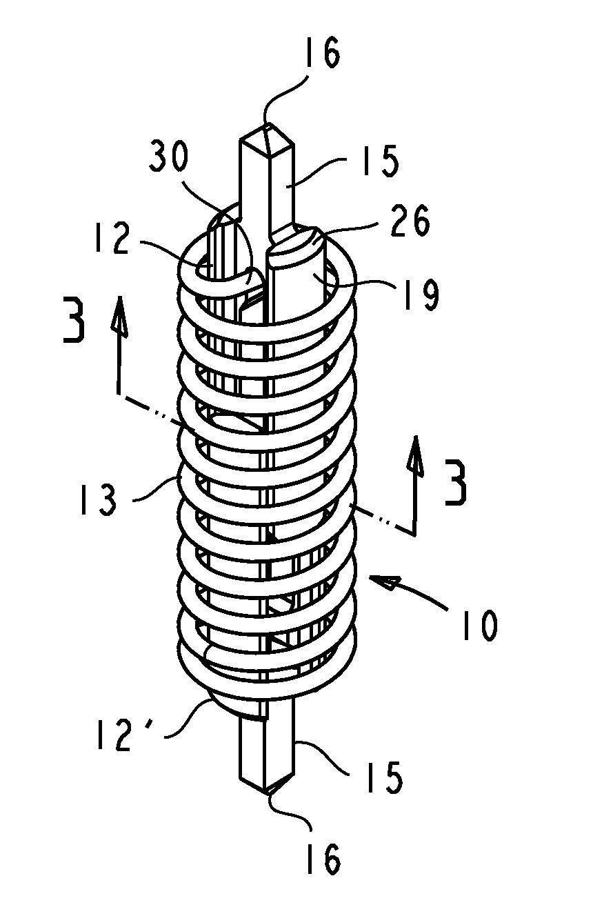
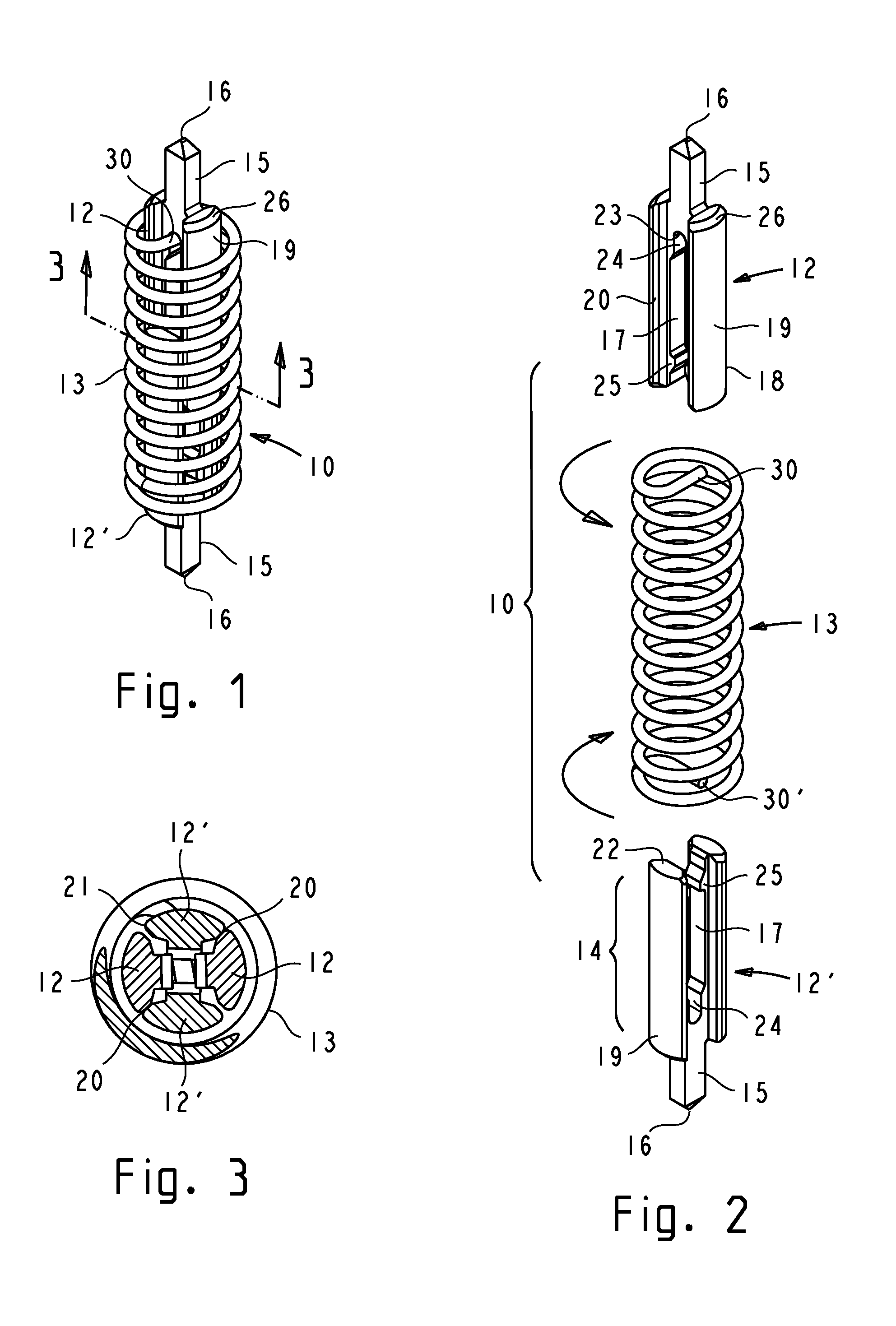
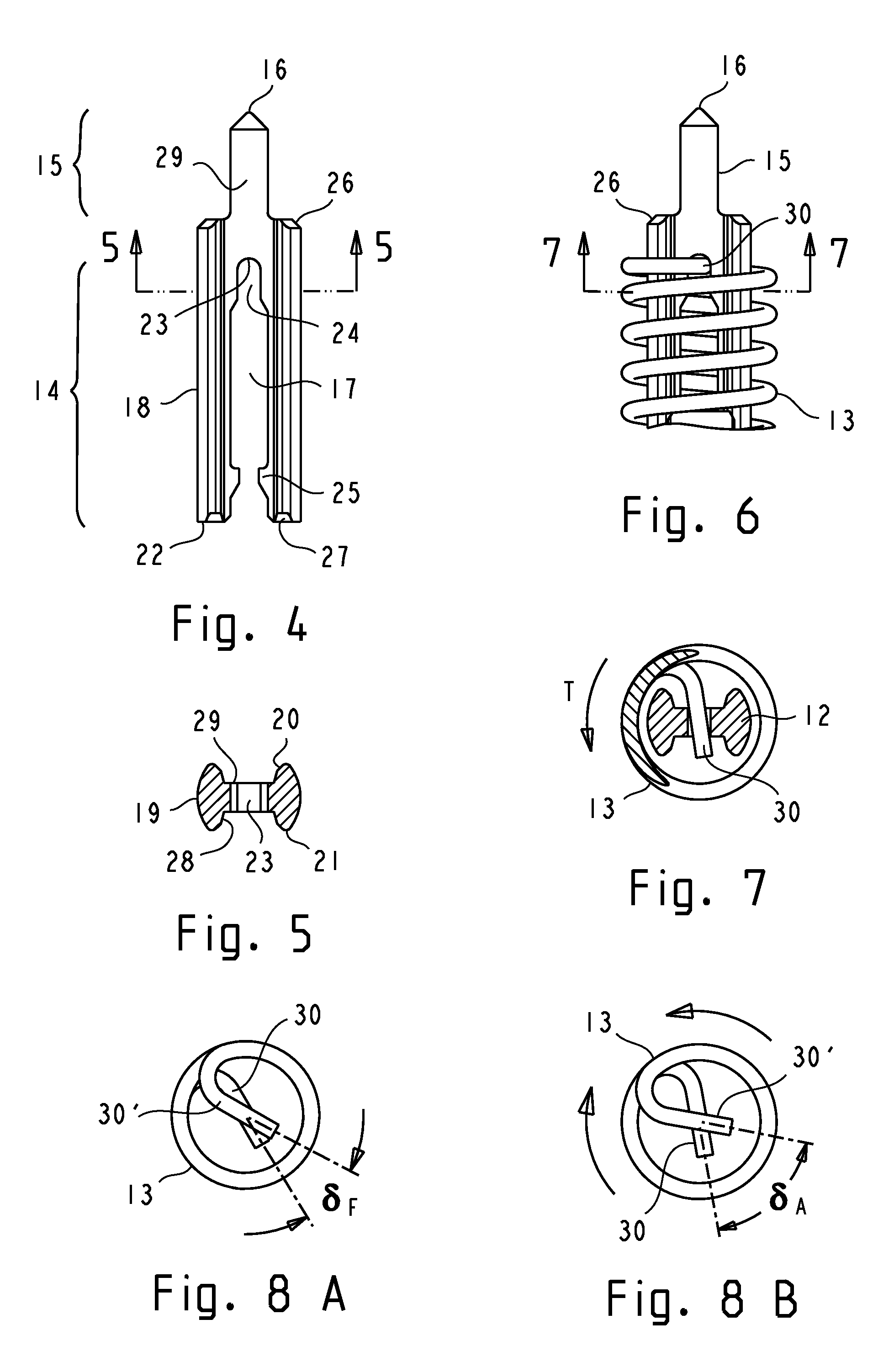
[0068]The disclosed contact probes are utilized in interposer sockets and connectors for separably connecting oppositely disposed electronic devices having complementary I / O terminal arrays. “First device” will generally refer to the device that is being plugged or connected whereas “second device” will generally refer to the next level device or hardware to which the first device is being separably connected, usually represented by a PCB. The “first plunger” is disposed to contact the first device and is shown on the top side of the contact probe drawings, whereas the “second plunger” is disposed to contact the second device and is shown on the bottom side of the contact probe drawings. Otherwise, a contact probe can have identical, interchangeable plungers and the devices can have identical terminal type (e.g., LGA pads). In the cases where the plungers are identical or have substantially similar features, they are denoted by the same reference numerals, except the reference numer...


PUM


Abstract

A contact probe comprises conductively coupled plungers and a coil spring. The plungers have coupling means which enable them to be slidably and non-rotatably engaged. The spring is attached to the plungers in a manner that prevents rotation of the spring's ends. A desired magnitude of torsional bias is generated by twisting the spring a predetermined angle prior to attachment of the spring to the plungers. An additional torsional bias is generated by the tendency of the spring to twist when the spring is axially displaced. The resultant torsional bias rotatably biases the coupling means of the plungers against each other, generating contact forces for a direct conductive coupling between the plungers. The plungers are self-latching or are retentively attached to the spring using the torsional bias of the spring. Plungers with hermaphroditic coupling means can be fabricated from a sheet metal or a profiled stock by stamping or machining.

Description

CROSS-REFERENCE TO RELATED APPLICATIONS[0001]This is a continuation-in-part of application No. 13 / 465,014 filed May 6, 2012BACKGROUND OF THE INVENTION[0002]1. Technical Field[0003]The present invention relates generally to electrical probes and contacts for interconnecting integrated circuit (IC) devices and electronic components and systems, and specifically, to miniature high speed circuit probes and contacts for separably interconnecting IC devices such as bare chips, IC packages, and electronic modules, to other devices, motherboards, test systems, and alike.[0004]2. Background Art[0005]Contact probes are typically used in interposer sockets which provide separable interfaces for two oppositely disposed devices having corresponding input / output (I / O) patterns. A typical application is an electrical socket for connecting an IC device to the next level of electronic hardware or to a test unit. The contact probes are positioned and maintained in a required array by an insulating ho...

Claims


Application Information

Patent Timeline
IPC IPC(8): G01R31/00
CPCH01R13/2421G01R1/06722H01R12/7082H01R12/714H01R2201/20
Inventor SOCHOR, JERZY ROMAN
Owner SOCHOR JERZY ROMAN
Why Eureka
Try Eureka