Electric motor and electrical machinery equipped therewith
a technology of electric motors and electrical machinery, applied in the direction of dynamo-electric components, magnetic circuit rotating parts, magnetic circuit shapes/forms/construction, etc., can solve the problems of abnormal sound, electric motors, electrolytic corrosion in bearings, etc., to prevent electrolytic corrosion, reduce potential differences, and raise the impedance of the rotor side
- Summary
- Abstract
- Description
- Claims
- Application Information
AI Technical Summary
Benefits of technology
Problems solved by technology
Method used
Image
Examples
first exemplary embodiment
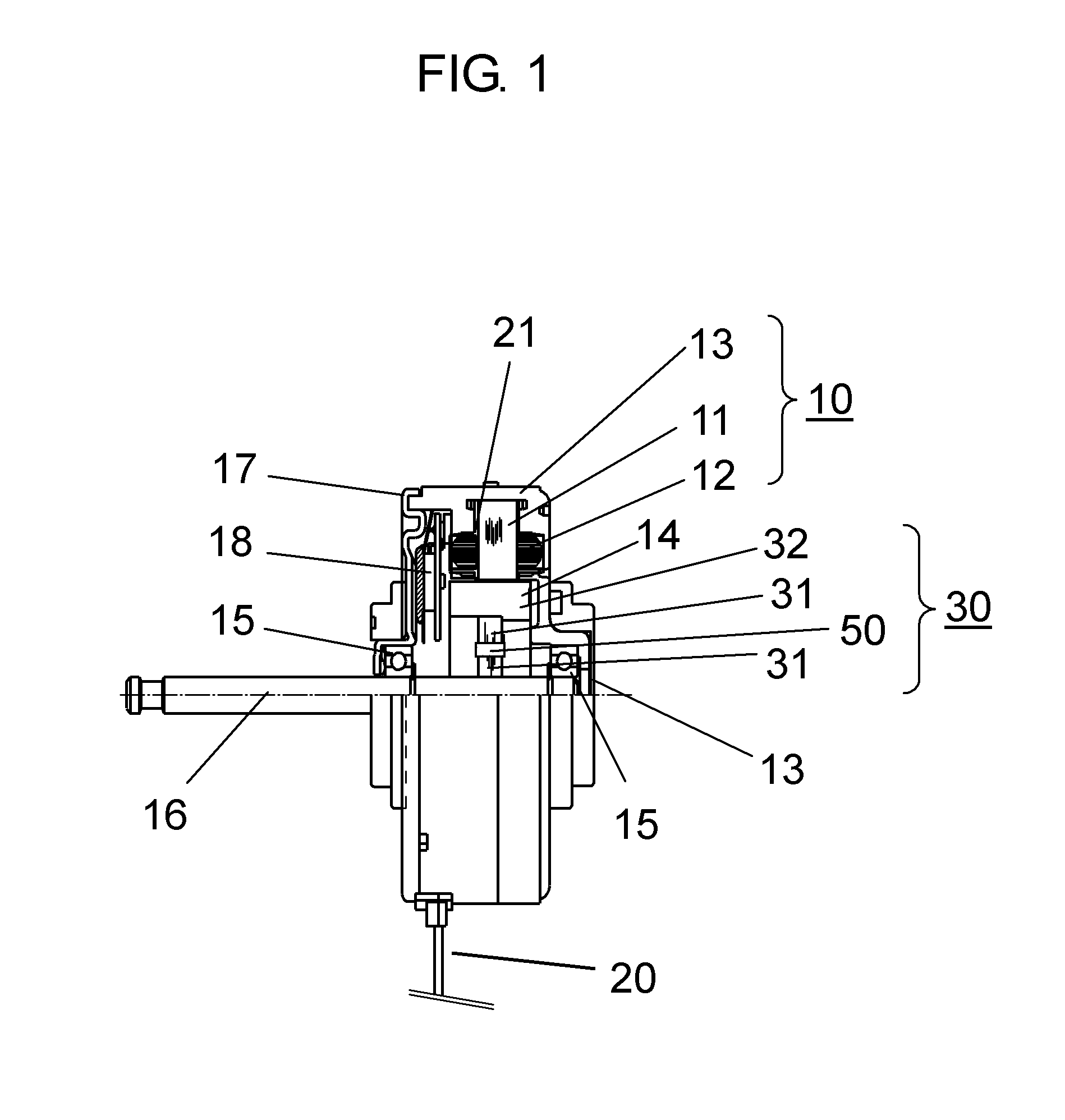
[0048]FIG. 1 is a configuration diagram showing a section of an electric motor in a first embodiment. In the present embodiment, a description will be given of an example of an electric motor which is loaded in an air conditioner as electric machinery and is a brushless motor for driving a blast fan. Furthermore, in the present embodiment, an example of an inner rotor type of an electric motor in which a rotor is rotatably disposed in an inner periphery side of a stator.
[0049]In FIG. 1, stator 10 is configured by molding stator steel core 11 around which stator coil 12 is wounded, with insulating resin 13 that is a mold material for integral molding. Furthermore, between stator steel core 11 and stator coil 12, resin 21 as an insulator for insulating stator steel core 11 is disposed.
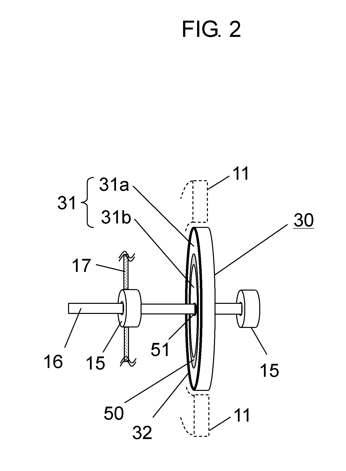
[0050]Rotor 14 is inserted into an inner side of stator 10 via a gap. Stator 14 has disc-shaped rotating body 30 including rotor steel core 31, and shaft 16 which fastens rotating body 30 so as to penetr...
first example
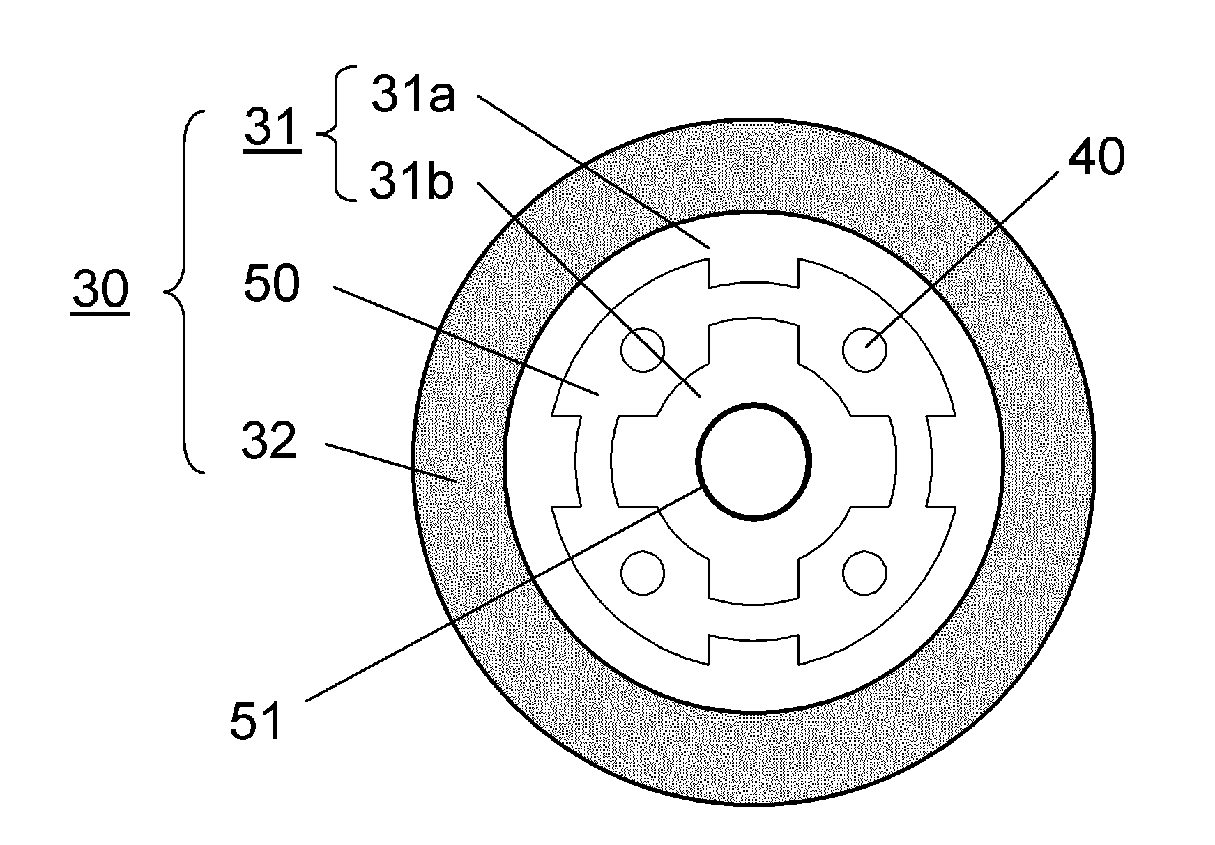
[0067]FIG. 6 is a diagram showing a sectional surface of the rotor of the brushless motor used in the first embodiment. As shown in FIG. 6, the portion between rotor steel core 31 and shaft 16 is insulated by dielectric layer 50.
[0068]By changing the inner diameter of rotor steel core 31, the axial voltage when changing the thickness of the insulating resin forming dielectric layer 50 was measured. The insulating resin material was implemented by two types of the PBT resin having the permittivity of 3.6 and the SPS resin having the permittivity of 2.8. Furthermore, the measurement was performed in a manner in which the same stator is used and the respective rotors are exchanged. As the bearing, Minebea 608 (lubricant of 239 is used) was used.
[0069]FIG. 7 is a diagram showing the measurement method of the axial voltage of the first embodiment. When measuring the axial voltage, a stabilized DC power supply was used, the power supply voltage Vdc of the coil was 391 V, and the power sup...
second example
[0078]In the second embodiment, the measurement of the impedance was performed by the same brushless motor as the first embodiment.
[0079]In the measurement of the impedance, NF circuit design block LCR meter ZM2353 and test lead 2325A were used to measure the impedance of the power supply voltage Vdc between the lead line of the coil and shaft 16. In addition, in the non rotation state, the brushless motor orientation was shaft horizontal and the measurement conditions were a voltage of 1 V and frequency of 10 kHz.
[0080]Furthermore, in order to confirm the impedance state during driving, the axial potential during driving was measured.
[0081]FIG. 11 shows a diagram of the measurement method of the axial potential of the second embodiment. The driving state and the driving condition were the same as the first embodiment, and the measurement of the axial voltage was performed so that a voltage wave form was observed by digital oscilloscope 130 (Techtronics DPO7104) and passive probe 15...
PUM
 Abstract
Description
Claims
Application Information
 - R&D
- Intellectual Property
- Life Sciences
- Materials
- Tech Scout
- Unparalleled Data Quality
- Higher Quality Content
- 60% Fewer Hallucinations
Browse by: Latest US Patents, China's latest patents, Technical Efficacy Thesaurus, Application Domain, Technology Topic, Popular Technical Reports.
© 2025 PatSnap. All rights reserved.Legal|Privacy policy|Modern Slavery Act Transparency Statement|Sitemap|About US| Contact US: help@patsnap.com


