Liquid-ejecting head, liquid-ejecting apparatus, and piezoelectric element

a piezoelectric element and liquid-ejecting head technology, applied in the direction of inking apparatus, device material selection, generator/motor, etc., can solve the problems of low insulating capacity of bifeosub>3/sub>-based piezoelectric materials and generate leakage current, and achieve excellent deformation characteristics, excellent piezoelectricity, and high reliability

Inactive Publication Date: 2013-11-05
SEIKO EPSON CORP
View PDF42 Cites 2 Cited by
  • Summary
  • Abstract
  • Description
  • Claims
  • Application Information

AI Technical Summary

Benefits of technology

[0009]In accordance with one aspect of the invention to solve the problems described above, a liquid-ejecting head includes a pressure-generating chamber and a piezoelectric element. The pressure-generating chamber communicates with a nozzle opening. The piezoelectric element includes a first electrode, a piezoelectric layer containing bismuth lanthanum iron-manganese oxide disposed on the first electrode, and a second electrode disposed on the first electrode of the piezoelectric layer. The integrated intensity of a diffraction peak observed at 20°<2θ<25° is 90% or more of the sum of the integrated intensities of diffraction peaks observed at 20°<2θ<50° in an X-ray powder diffraction pattern of the piezoelectric layer measured at φ=Φ=0°. Since the liquid-ejecting head includes the piezoelectric element including the lead-free piezoelectric layer containing bismuth lanthanum iron-manganese oxide, the liquid-ejecting head has excellent deformation characteristics.
[0010]Preferably, the first electrode includes a first titanium oxide layer containing titanium oxide, a platinum layer containing platinum disposed on the first titanium oxide layer, and a second titanium oxide layer containing titanium oxide disposed on the platinum layer, and the piezoelectric layer is disposed on the second titanium oxide layer. This facilitates the formation of a piezoelectric layer containing bismuth lanthanum iron-manganese oxide in which crystals are preferentially oriented in a (100) plane. The phrase “preferentially oriented in a (100) plane”, as used herein, includes both cases where all the crystals are oriented in the (100) plane and almost all the crystals (for example, 90% or more) are oriented in the (100) plane.
[0011]Preferably, the first electrode includes a platinum layer containing platinum and a lanthanum nickel oxide (LNO) layer containing lanthanum nickel oxide disposed on the platinum layer, the LNO layer having a thickness of 50 nm or more, and the piezoelectric layer is disposed on the LNO layer. Thus, the piezoelectric layer containing bismuth lanthanum iron-manganese oxide in which crystals are preferentially oriented in the (100) plane can be easily formed on the first electrode, which includes the platinum layer and the LNO layer.
[0012]Preferably, the bismuth lanthanum iron-manganese oxide is a complex oxide having a general formula (1) described below. Since the complex oxide having the general formula (1) can have the characteristics of a ferroelectric substance, the liquid-ejecting head can include a lead-free piezoelectric element the strain of which is easy to control. Thus, the liquid-ejecting head can include a piezoelectric element that can easily control the size of droplets ejected.(Bi1-x,Lax)(Fe1-y,Mny)O3  (1)(0.10≦x≦0.20,0.01≦y≦0.09)
[0014]In accordance with another aspect of the invention, a liquid-ejecting apparatus includes such a liquid-ejecting head as described above. In accordance with this aspect, since the liquid-ejecting head includes a lead-free piezoelectric element having excellent deformation characteristics, the liquid-ejecting apparatus does not adversely affect the environment and has high reliability.
[0015]A piezoelectric element according to an aspect of the invention includes a piezoelectric layer containing bismuth lanthanum iron-manganese oxide, and an electrode disposed on the piezoelectric layer, wherein the integrated intensity of a diffraction peak observed at 20°<2θ<25° is 90% or more of the sum of the integrated intensities of diffraction peaks observed at 20°<2θ<50° in an X-ray powder diffraction pattern of the piezoelectric layer measured at φ=Φ=0°. Thus, the piezoelectric element is free of lead and has excellent piezoelectricity.

Problems solved by technology

However, BiFeO3-based piezoelectric materials have low insulating capacity and sometimes generate leakage current.
These problems are not confined to liquid-ejecting heads, including ink jet print heads, and also occur in piezoelectric elements, such as actuators, contained in other apparatuses.

Method used


Image

  • Liquid-ejecting head, liquid-ejecting apparatus, and piezoelectric element
  • Liquid-ejecting head, liquid-ejecting apparatus, and piezoelectric element
  • Liquid-ejecting head, liquid-ejecting apparatus, and piezoelectric element

Examples


first embodiment

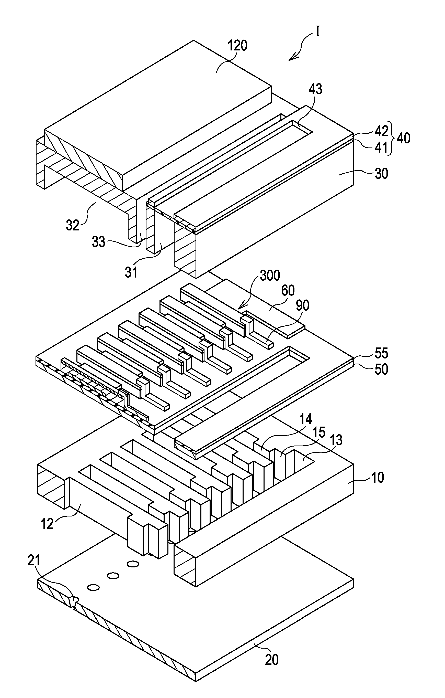
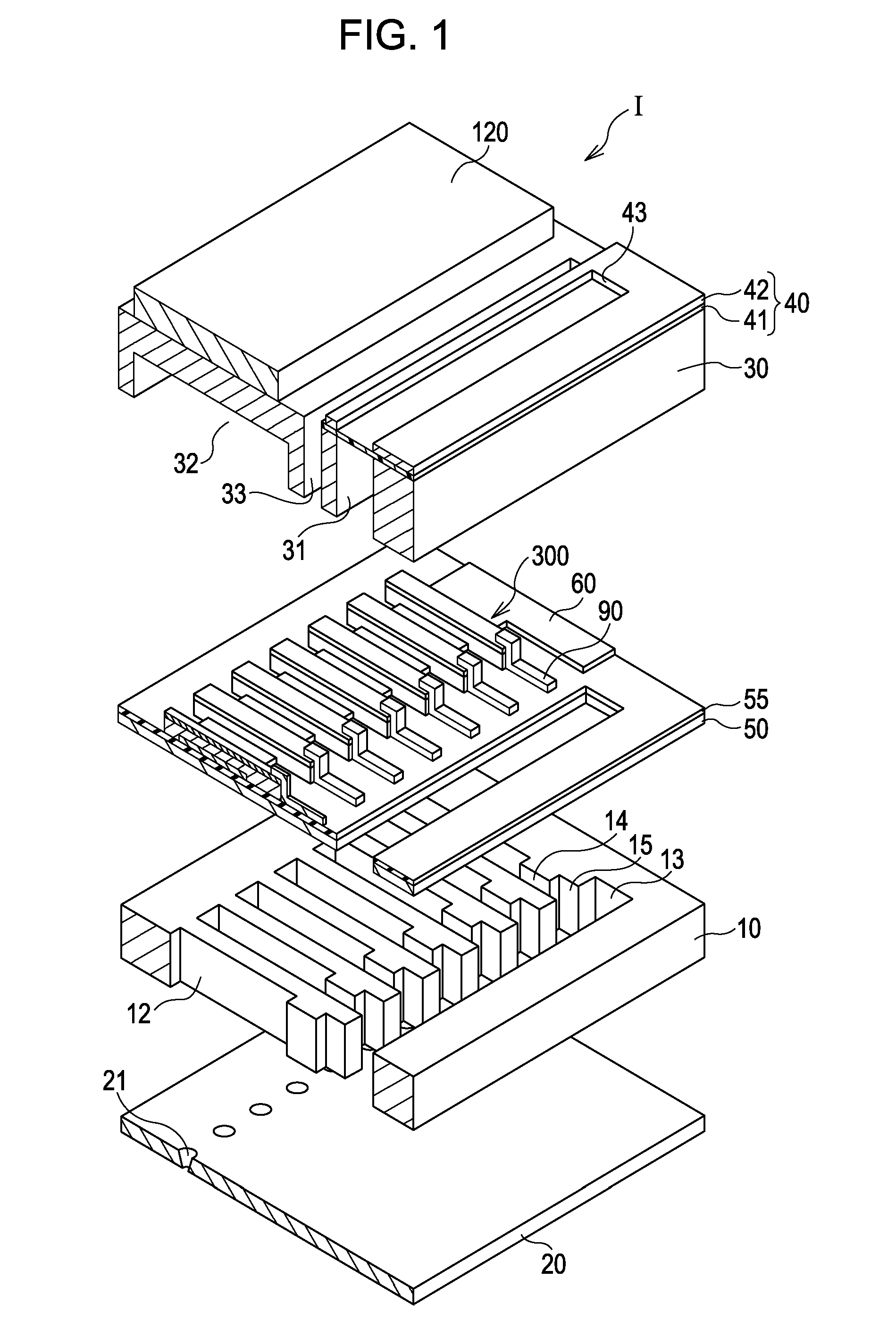
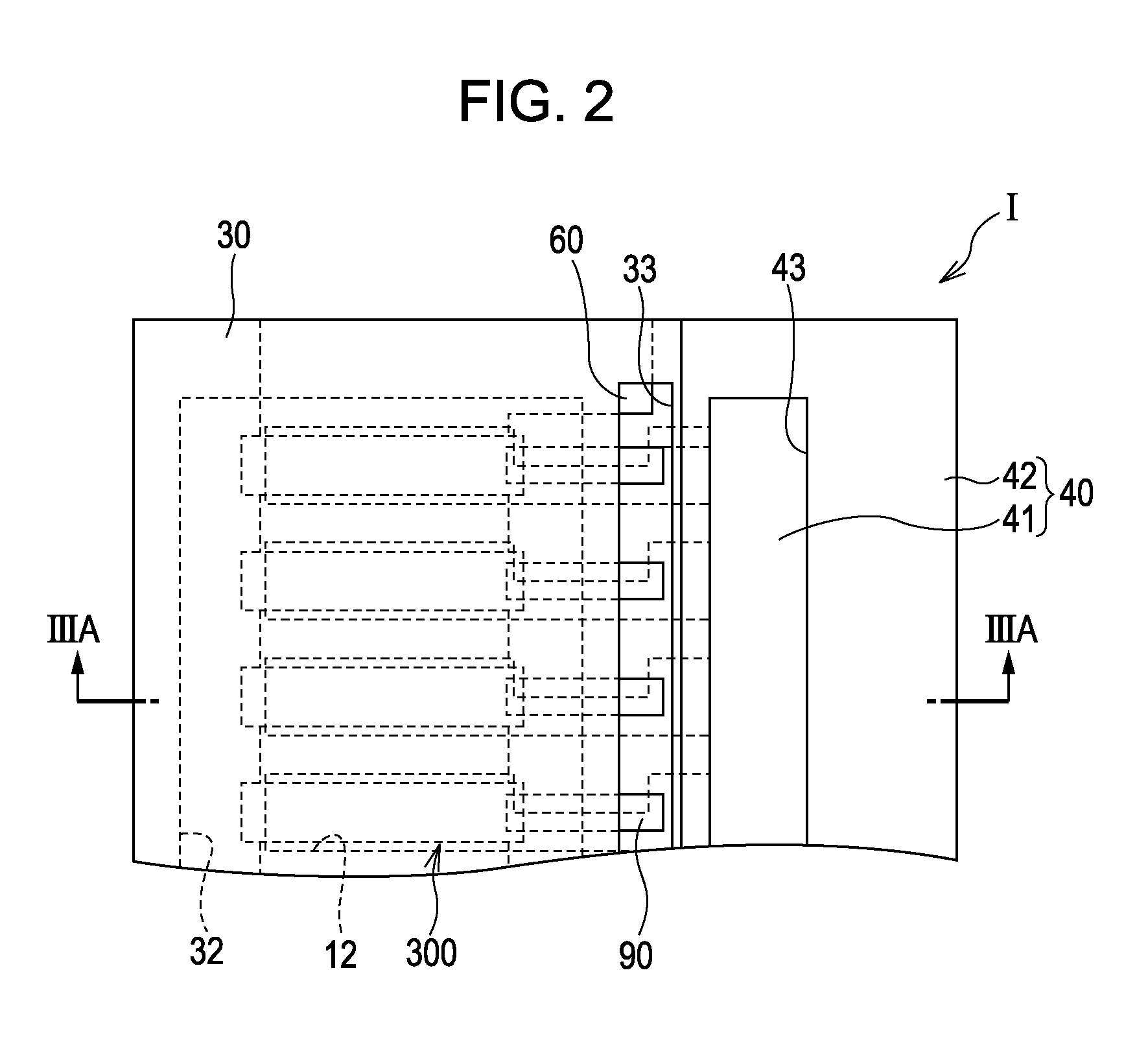
[0055]FIG. 1 is a schematic exploded perspective view of an ink jet print head as an example of a liquid-ejecting head manufactured by a method according to a first embodiment of the invention. FIG. 2 is a fragmentary plan view of the print head according to the first embodiment. FIG. 3A is a cross-sectional view of the print head taken along the line IIIA-IIIA of FIG. 2. FIG. 3B is an enlarged cross-sectional view of a principal part of the print head according to the first embodiment.

[0056]As illustrated in FIGS. 1 and 3, a flow-passage-forming substrate 10 according to the present embodiment is a silicon single crystal substrate. A silicon dioxide elastic film 50 is disposed on the flow-passage-forming substrate 10.

[0057]The flow-passage-forming substrate 10 includes a plurality of pressure-generating chambers 12 juxtaposed to each other in the width direction. The flow-passage-forming substrate 10 further includes a communication portion 13 outside the pressure-generating chambe...

example 1

[0106]A surface of a silicon substrate was thermally oxidized to form a silicon dioxide film. A zirconium oxide film having a thickness of 400 nm was then formed on the silicon dioxide film by RF sputtering. A titanium film having a thickness of 20 nm was then formed on the zirconium oxide film by DC sputtering. A platinum film having a thickness of 130 nm was then formed on the titanium film by DC sputtering.

[0107]A piezoelectric layer was then formed on the platinum film by spin coating in the following manner. First, solutions of bismuth 2-ethylhexanoate, lanthanum 2-ethylhexanoate, iron 2-ethylhexanoate, or manganese 2-ethylhexanoate in xylene and octane were mixed at a predetermined ratio to prepare a precursor solution. The precursor solution was dropped onto the substrate on which the platinum film was disposed. The substrate was initially rotated at 500 rpm for five seconds and subsequently 1500 rpm for 30 seconds to form a piezoelectric precursor film (a coating step). Dryi...

example 2

[0109]A piezoelectric element according to Example 2 was formed in the same manner as in Example 1 except that a lanthanum nickel oxide (LNO) layer having a thickness of 50 nm was formed on a platinum film by RF sputtering. For comparison purposes, a piezoelectric element including a LNO layer having a thickness of 10 nm was also fabricated.


PUM


Abstract

A piezoelectric element comprising a first electrode, a piezoelectric layer which includes bismuth, lanthanum iron, and manganese and which formed above the first electrode and a second electrode formed above the piezoelectric layer. The integrated intensity of a diffraction peak observed at 20°<2θ<25° is 90% or more of the sum of the integrated intensities of diffraction peaks observed at 20°<2θ<50° in an X-ray powder diffraction pattern of the piezoelectric layer measured at φ=Φ=0°.

Description

CROSS-REFERENCE TO RELATED APPLICATIONS[0001]This application claims the benefit of priority to Japanese Patent Application No. 2010-000829 filed Jan. 5, 2010, the contents of which are hereby incorporated by reference in their entirety.BACKGROUND[0002]1. Technical Field[0003]The present invention relates to a piezoelectric element, a liquid-ejecting head including the piezoelectric element, and a liquid-ejecting apparatus including the piezoelectric element. The piezoelectric element includes a piezoelectric layer and electrodes through which a voltage is applied to the piezoelectric layer. The piezoelectric element produces a pressure change in a pressure-generating chamber in communication with a nozzle opening.[0004]2. Related Art[0005]One example of piezoelectric elements for use in liquid-ejecting heads includes a piezoelectric layer between two electrodes. The piezoelectric layer is formed of a piezoelectric material having an electromechanical transfer function, such as a cr...

Claims


Application Information

Patent Timeline
Patent Type & Authority Patents(United States)
IPC IPC(8): B41J2/045B05C5/00B41J2/055B41J2/135B41J2/14H01L41/047H01L41/08H01L41/09H01L41/18H01L41/187H01L41/22H01L41/29H01L41/317H01L41/319H01L41/39
CPCB41J2/055B41J2/161B41J2/1629B41J2/1634B41J2/1642B41J2/1646H01L41/319H01L41/0815H01L41/0973H01L41/1878H01L41/317B41J2202/03B41J2002/14241H10N30/10516H10N30/2047H10N30/8561H10N30/079H10N30/078
Inventor NAWANO, MASAHISA
Owner SEIKO EPSON CORP
Why Eureka
Try Eureka