
Light-emitting device, method for manufacturing same, molded body and sealing member

a technology of light-emitting devices and moldings, which is applied in the direction of synthetic resin layered products, chemistry apparatuses and processes, layered products, etc., can solve the problems of poor adhesion of resins to leads and sealing members, resins that use silicone resins lack long-term reliability, and prior art thermoplastic resins used as moldings in surface-mounted light-emitting devices are less resistant to light, etc. , to achieve the effect of adversely affecting

Active Publication Date: 2013-11-05
NICHIA CORP
View PDF33 Cites 49 Cited by
  • Summary
  • Abstract
  • Description
  • Claims
  • Application Information

AI Technical Summary

Benefits of technology

The invention relates to a curing agent for epoxy resins that improves their heat and light resistance. The curing agent is a combination of acid anhydride and a triazine derived epoxy resin. The amount of acid anhydride curing agent is important - between 0.5 to 2.0 equivalents per equivalent of epoxy resin is preferred. If the amount is too low, the curing may not be complete and the moisture resistance of the cured product may be adversely affected. If the amount is too high, unreacted curing agent may be left in the cured product. In addition, the epoxy resin can be combined with other epoxy resins, such as bisphenol A type epoxy resins or biphenol type epoxy resins, in amounts below a certain level to ensure the effect of the invention is not compromised.

Problems solved by technology

However, prior art thermoplastic resins used as moldings in surface mount light-emitting devices are less resistant to light due to the inclusion of an aromatic component within the molecule although they are resistant to heat.
Also, since hydroxyl groups or other groups for improving adhesion are absent at molecular ends, the resins exhibit poor adhesion to leads and sealing members.
In particular, sealing members using silicone resins lack long-term reliability since they show a drastic drop in adhesion to molded parts using thermoplastic resins, as compared with sealing members using epoxy resins.
Epoxy resins are used as sealing members, but not as molded parts in leadframe type surface mount devices because of their difficulty to mold.
Thus, degradation of molded parts becomes a problem when light-emitting elements of blue emission are used.
These epoxy resins, however, are not solid materials obtained by reacting a triazine derived epoxy resin with an acid anhydride.

Method used


Image

  • Light-emitting device, method for manufacturing same, molded body and sealing member
  • Light-emitting device, method for manufacturing same, molded body and sealing member
  • Light-emitting device, method for manufacturing same, molded body and sealing member

Examples


example

[0092]Examples and Comparative Examples are given below for further illustrating the invention although the invention is not limited to these Examples.

examples 1 to 10

[0093]Of the components shown in Table 1, the epoxy resin, acid anhydride and antioxidant were previously melt mixed on a reactor at 100° C. for 3 hours. The mixture was cooled for solidification (softening point 60° C.), ground, and thereafter compounded with other components in the predetermined compositional ratio. This was uniformly melt mixed on a hot twin-roll mill, cooled, and ground, yielding a cured product of a white epoxy resin composition serving as a molded part for use in a light-emitting device. The starting materials used herein are described below.[0094](A) Epoxy resin[0095](A-1) Triazine Derived Epoxy Resin[0096](i) Tris(2,3-epoxypropyl) isocyanate (trade name TEPIC-S by Nissan Chemical Industries, Ltd., epoxy equivalent 100)[0097](A-2) Hydrogenated epoxy resin[0098](ii) Hydrogenated bisphenol A type epoxy resin (trade name YL-7170 by Japan Epoxy Resins Co., Ltd., epoxy equivalent 1200)[0099](iii) Hydrogenated biphenyl type epoxy resin (trade name YL-7040 by Japan ...

example 11

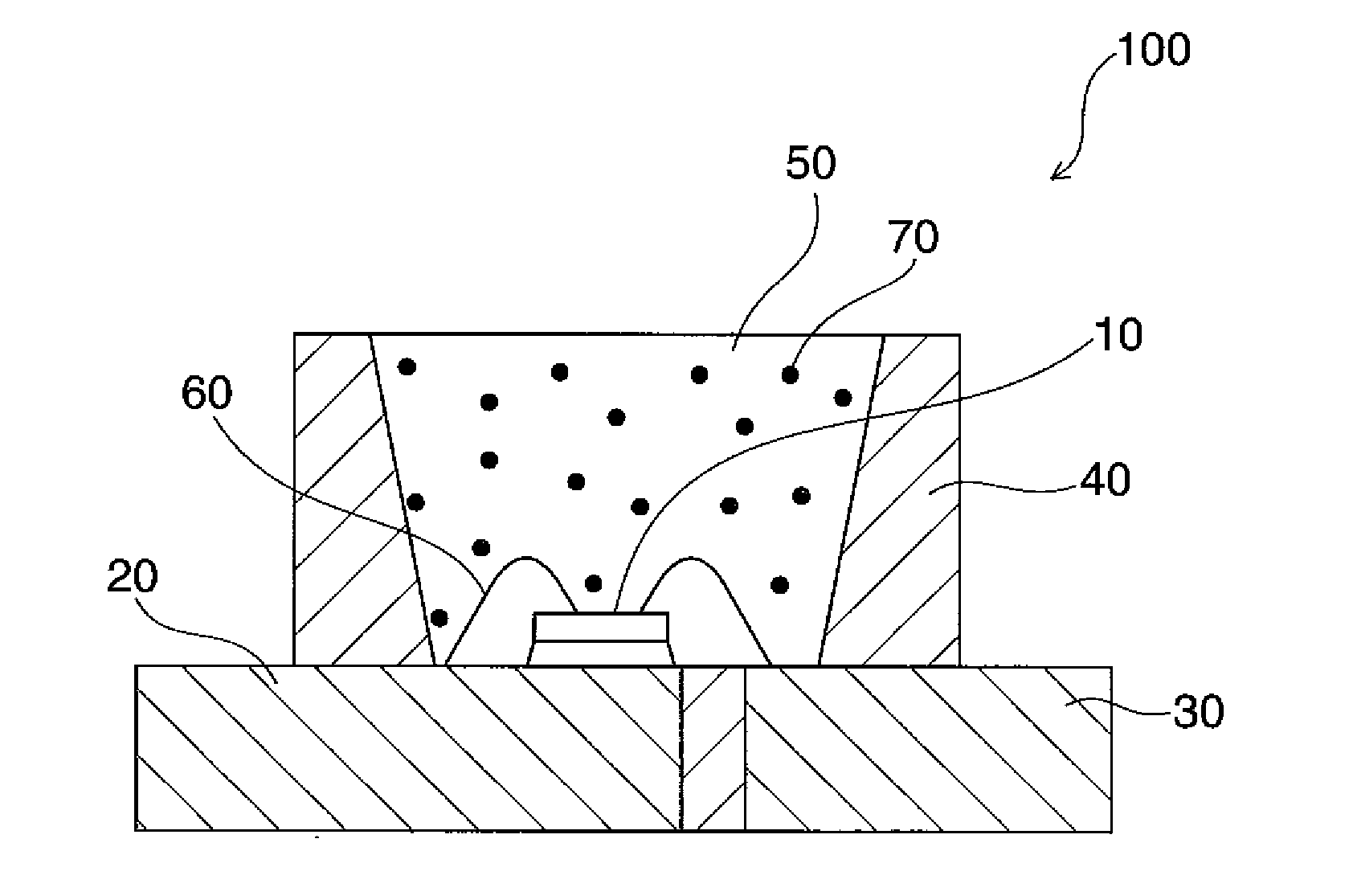
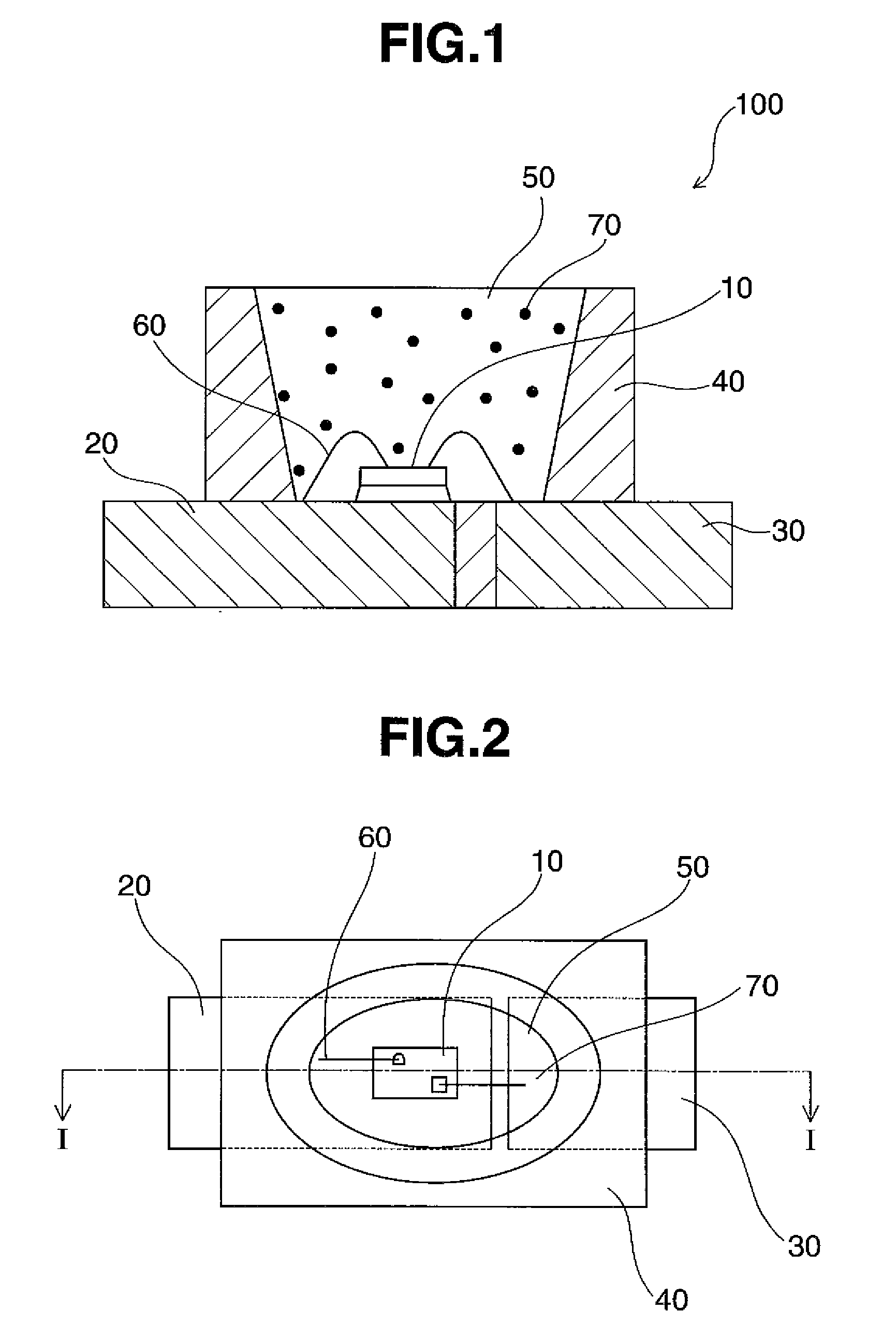
[0127]Example 11 demonstrates a light-emitting device. In the light-emitting device of Example 11, an epoxy resin composition according to the invention is molded to form a molded part on a leadframe of copper alloy by a transfer molding technique. The molded part is provided with a recess having bottom and side surfaces. A light-emitting element of blue emission comprising a sapphire substrate and a light-emitting layer of InGaN is mounted using an epoxy resin adhesive. The light-emitting element is electrically connected to the leadframe using gold wires having a diameter of 30 μm. A sealing member is applied dropwise into the molded part with the recess on the bottom surface of which the light-emitting element is mounted. The sealing member used contains 100 parts by weight of a silicone resin, 30 parts by weight of a YAG phosphor, and 5 parts by weight of a light diffuser of silicon oxide. It is heated from room temperature to 150° C. over 3 hours, and cured at 150° C. for 5 hou...


PUM

PropertyMeasurementUnit
emission peak wavelengthaaaaaaaaaa
reflectanceaaaaaaaaaa
softening pointaaaaaaaaaa

Abstract

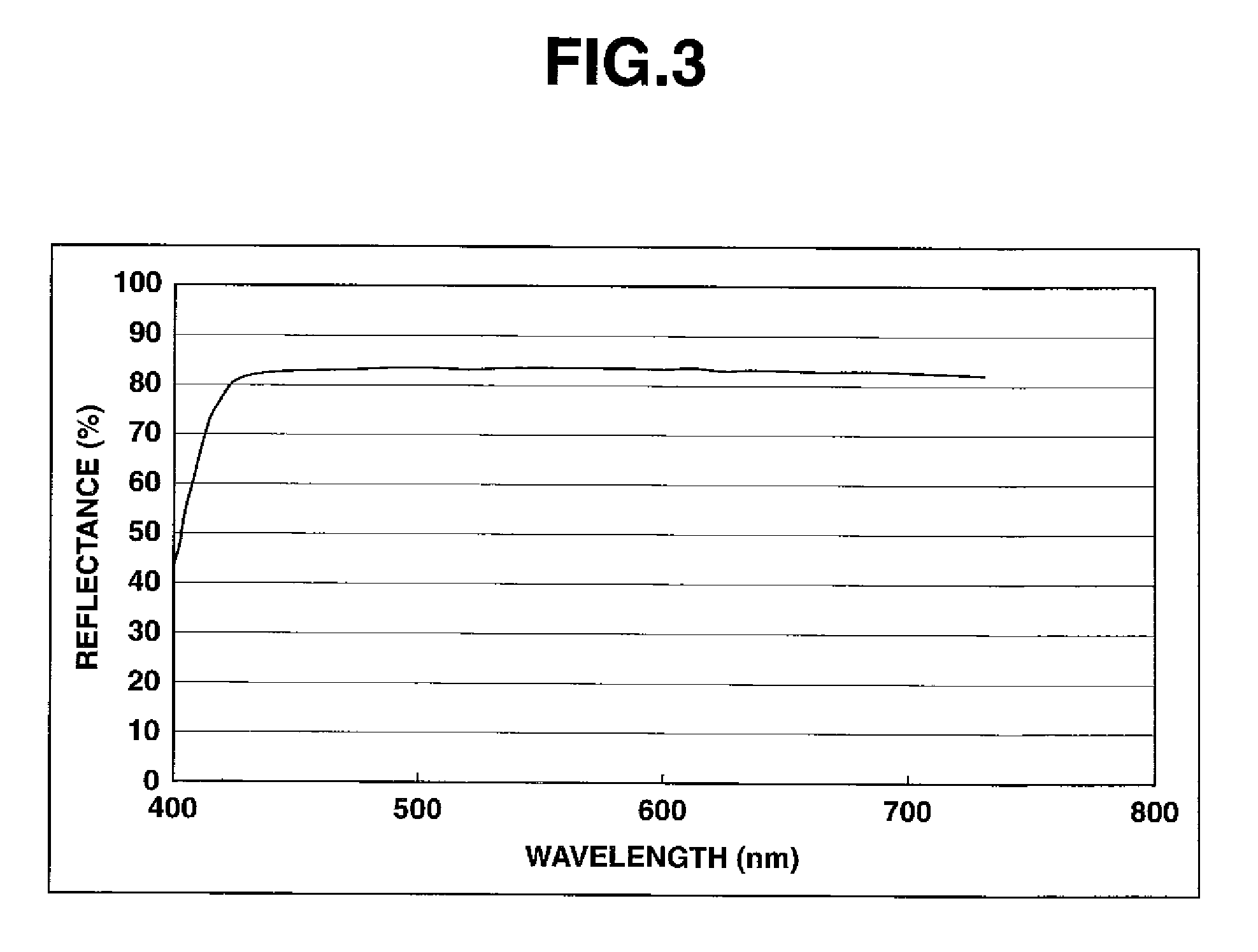
Disclosed is a light-emitting device comprising a light-emitting element (10) composed of a gallium nitride compound semiconductor having an emission peak wavelength of not less than 430 nm; a molded body (40) provided with a recessed portion having a bottom surface on which the light-emitting element (10) is mounted and a lateral surface; and a sealing member (50) containing an epoxy resin including a triazine derivative epoxy resin, or a silicon-containing resin. The molded body (40) is obtained by using a cured product of a thermosetting epoxy resin composition essentially containing an epoxy resin including a triazine derivative epoxy resin, and has a reflectance of not less than 70% at the wavelengths of not less than 430 nm.

Description

TECHNICAL FIELD[0001]This invention relates to a light-emitting device for use as luminaires, displays, mobile phone backlights, moving picture illuminating auxiliary light sources, and other general commercial light sources, a method for preparing the same, a molded part, and a sealing member.BACKGROUND ART[0002]Surface mount light-emitting devices using light-emitting elements feature a small size, a good power efficiency, and light emission of brilliant color. The light-emitting elements eliminate the risk of lamp failures since they are semiconductor elements. They are also characterized by improved initial drive performance and resistance to vibration and repeated turn-on and off. Because of these improved properties, light-emitting devices using light-emitting elements such as light-emitting diodes (LED) and laser diodes (LD) are utilized as light sources in varying applications. Recently, light-emitting elements have marked a rapid advance toward higher outputs.[0003]For the ...

Claims


Application Information

Patent Timeline
Patent Type & Authority Patents(United States)
IPC IPC(8): H01L33/32H01L33/60H01L33/00C08L63/00H01L33/56
CPCC08G59/3245H01L33/36H01L33/56H01L33/60H01L33/32C08K5/005H01L2224/0603H01L2224/48091H01L2224/48247H01L2224/48257H01L2224/73265H01L2924/01004H01L2924/01057H01L2924/01079C08K3/0033H01L2224/45144H01L2924/01067H01L2924/01019H01L2224/32245H01L2924/00014H01L2924/00C08K3/013H01L2924/00012
Inventor KURAMOTO, MASAFUMIMIKI, TOMOHIDETSUKIOKA, TOMOYAKISHIMOTO, TOMOHISA
Owner NICHIA CORP
Learn More