
Planarization of a material system in a semiconductor device by using a non-selective in situ prepared slurry

a semiconductor device and material system technology, applied in the field of manufacturing integrated circuits, can solve the problems of mechanical damage to the polished surface, different removal rates of different materials, inferior process conditions for subsequent processes and structural features,

Active Publication Date: 2013-11-19
TAIWAN SEMICON MFG CO LTD
View PDF34 Cites 2 Cited by
  • Summary
  • Abstract
  • Description
  • Claims
  • Application Information

AI Technical Summary

Benefits of technology

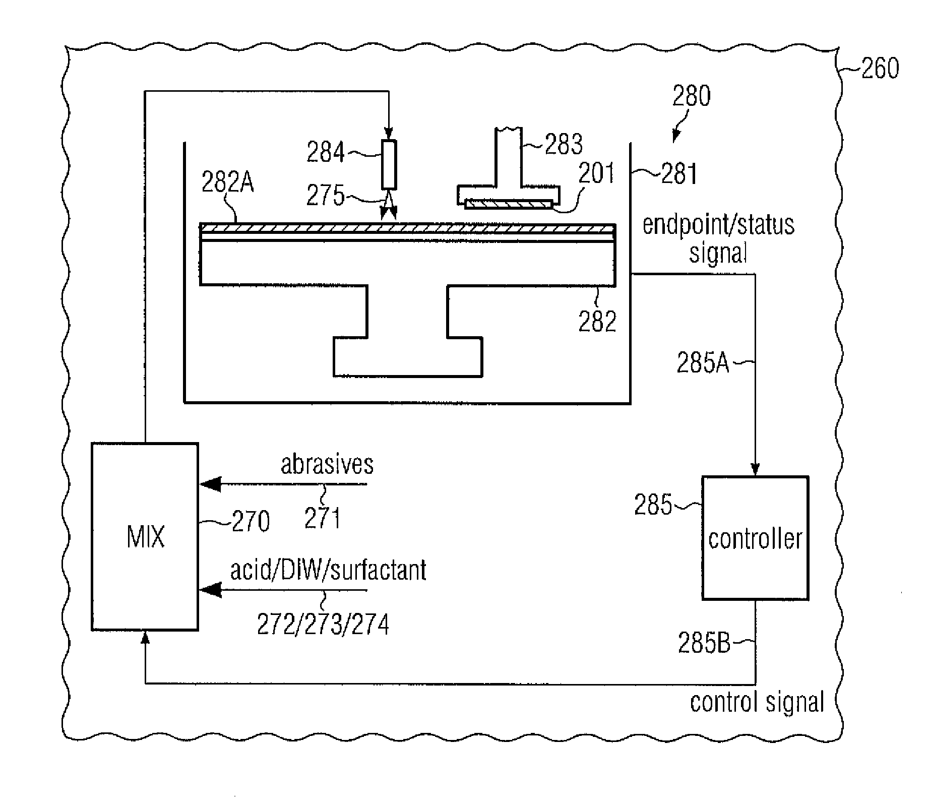
The present patent provides a process technique and system for achieving superior uniformity during chemical mechanical planarization of complex material systems including at least two different dielectric materials. The technique involves adapting the slurry solution used for removal in a highly dynamic manner, by modifying it at the point of use to provide substantially matched removal rates for the various materials of the system. This flexibility allows for better control of complex removal processes and superior controllability in the context of a replacement gate approach.

Problems solved by technology

The polishing process itself causes mechanical damage to the polished surface, however, in an extremely low range, i.e., at an atomic level, depending on the process conditions.
One problem involved in the chemical mechanical polishing of substrates is the very different removal rates of differing materials, such as of a metal and a dielectric material, or dielectric materials of different type, or dielectric materials and semiconductive materials.
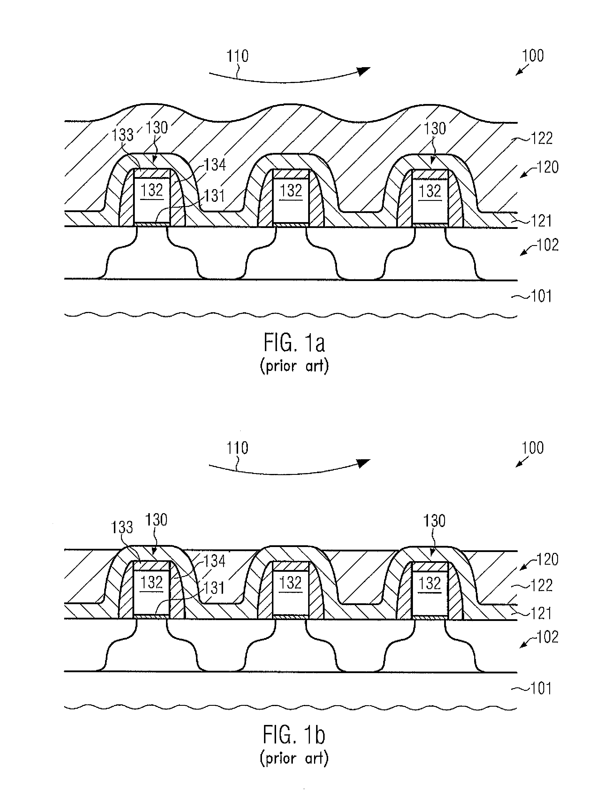
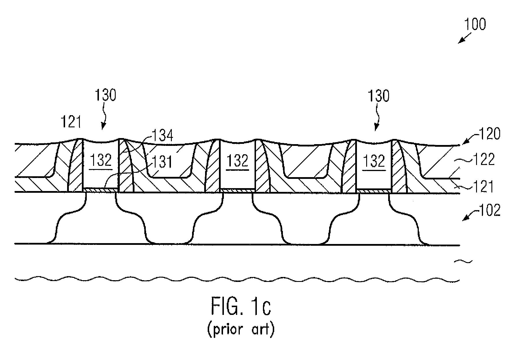
The different removal rates may, thus, contribute to a pronounced surface topography, wherein, typically, the material having the higher removal rate is increasingly recessed, which may, thus, result in inferior process conditions for subsequent processes and performance of structural features.
On the other hand, since a certain degree of overpolished time is typically required for completely removing the metal material across the entire substrate surface, a certain amount of the dielectric material may also be removed, however, in a pattern related manner, thereby also contributing to a non-planar surface topography after the end of the polishing process.
Consequently, although the CMP process technique is per se a promising approach for globally providing a planar surface topography, the removal of a material may require a specifically designed slurry solution, thereby enabling an appropriate adaptation of the process conditions to the specific manufacturing phase of a semiconductor device for one specific material, while the slurry may be less appropriate for the removal of another material.
In other situations, however, the different removal characteristics of silicon nitride and silicon dioxide may cause significant variations in device characteristics and may also negatively influence the further processing of complex semiconductor devices, in particular when even a third material has to be treated during a certain phase of the CMP process.
It turns out, however, that the limited number of commercially available slurry solutions having a substantially matched removal rate for silicon dioxide and silicon nitride have to be used within a very narrow process window, thereby contributing to a reduced degree of controllability, since any small variations in process conditions may result in an over-proportional deviation of the process result.
In this case, the recessed areas in the silicon dioxide material may require excessive overpolish times in order to reliably remove any metal residues, thereby generally reducing the overall height of the gate electrode structures, while nevertheless a certain probability of leaving any metal residues and, thus, leakage paths may exist.

Method used


Image

  • Planarization of a material system in a semiconductor device by using a non-selective in situ prepared slurry
  • Planarization of a material system in a semiconductor device by using a non-selective in situ prepared slurry
  • Planarization of a material system in a semiconductor device by using a non-selective in situ prepared slurry

Examples


Embodiment Construction

[0033]Various illustrative embodiments of the invention are described below. In the interest of clarity, not all features of an actual implementation are described in this specification. It will of course be appreciated that in the development of any such actual embodiment, numerous implementation-specific decisions must be made to achieve the developers' specific goals, such as compliance with system-related and business-related constraints, which will vary from one implementation to another. Moreover, it will be appreciated that such a development effort might be complex and time-consuming, but would nevertheless be a routine undertaking for those of ordinary skill in the art having the benefit of this disclosure.

[0034]The present subject matter will now be described with reference to the attached figures. Various structures, systems and devices are schematically depicted in the drawings for purposes of explanation only and so as to not obscure the present disclosure with details ...


PUM

PropertyMeasurementUnit
heightaaaaaaaaaa
heightaaaaaaaaaa
pHaaaaaaaaaa

Abstract

For complex CMP processes requiring the removal of different dielectric materials, possibly in the presence of a polysilicon material, a slurry material may be adapted at the point of use by selecting an appropriate pH value and avoiding agglomeration of the abrasive particles. The in situ preparation of the slurry material may also enable a highly dynamic adaptation of the removal conditions, for instance when exposing the polysilicon material of gate electrode structures in replacement gate approaches.

Description

BACKGROUND OF THE INVENTION[0001]1. Field of the Invention[0002]Generally, the subject matter disclosed herein relates to the field of manufacturing integrated circuits, and, more particularly, to chemical mechanical polishing (CMP) or generally planarizing processes and tools used for the formation of advanced semiconductor features, such as gate electrode structures, in which different materials have to be concurrently removed.[0003]2. Description of the Related Art[0004]The fabrication of modern integrated circuits requires a plurality of individual process steps involving the deposition of conductive, semiconductive or insulating layers on an appropriate substrate. After the deposition of one or more materials, device features are produced by patterning or otherwise treating the materials with well-known means, such as photolithography and etching. As a consequence, by patterning a material layer or layer system, typically, a certain topography will be created that also affects ...

Claims


Application Information

Patent Timeline
Patent Type & Authority Patents(United States)
IPC IPC(8): B24B1/00
CPCH01L21/31053H01L29/66545H01L29/7833
Inventor GROSCHOPF, JOHANNESHUESELITZ, RICOKITSCHE, MARCOSTEFFEN, KATJA
Owner TAIWAN SEMICON MFG CO LTD
Learn More