Centromere detector and method for determining radiation exposure from chromosome abnormalities

a technology of chromosome abnormalities and detectors, applied in the field of radiation exposure determination, can solve the problems of limiting the throughput of dcc assay, 50% misclassification of dcc, and obtaining accurate throughput, so as to facilitate better discrimination of dccs, improve the accuracy of centromere recognition, and improve the localization of centrifugal particles

Active Publication Date: 2013-12-10
CYTOGNOMIX
View PDF6 Cites 6 Cited by
  • Summary
  • Abstract
  • Description
  • Claims
  • Application Information

AI Technical Summary

Problems solved by technology

However, these techniques presented problems with obtaining an accurate throughput.
However, these manual, non-automatic techniques severely limit the throughput of the DCC assay.
Unfortunately, this system showed 50% misclassification of the DCC (Vaurijoux et al.
The reason for the high false detection was a faulty algorithm.
Another problem with the present methods of analyzing chromosomes is that an imprecise method of image segmentation is used to partition the chromosome's metaphase image into many non-overlapping regions that correspond to individual chromosome objects.
This causes error because chromosomes demonstrate high variability in shape on microscope slides mainly due to stages of cell cycle, length of mitotic arrest, slide preparation and banding patterns.
This presents a significant challenge for automated segmentation, as well as for extracting the centerline of a chromosome, requiring expert input (Moradi M et al., “Automatic locating the centromere on human chromosome pictures,” in 16th IEEE Symposium on Computer-Based Medical Systems, 2003; Moradi M and S K Saterandan, Pattern Recognition Letters, 27:19-28, 2006).
Furthermore, all of these methods are prone to effects of uneven illumination, which can segment spurious objects that are partially discontinuous.
Thresholded images are still sensitive to quantization errors present in the digital image.
Intensity fading is also evident, resulting in cropping at the boundaries of the chromosome object.
This method fails if branches form at a distance from the telomere, which is common in bent chromosomes.
Thinning procedures produce fewer spurious branches than skeletonization, however, the thinned result often has missing data at the chromosome ends (Lam L & S W Lee, IEEE Trans on Pattern Analysis &Machine Intelligence, 14:869-885, 1992; Jang B K and T C Roland, “Analysis of thinning algorithms using mathematical morphology,”IEEE Trans. on Pattern Analysis and Machine Intelligence (PAMI), 12(6), March 1990).
However, these approaches may still lead to spurious branches as well as bifurcations near telomeres.
Subsequent pruning of these branches is the major limitation of both MAT and thinning.
Both approaches are not reliable if chromosomes are highly bent or blurred.
However, the drawback of this method is that it attempts to get a polygonal approximation of the medial axis, instead of the medial axis itself and poor results were obtained when the segmented boundaries had irregular shapes.

Method used


Image

  • Centromere detector and method for determining radiation exposure from chromosome abnormalities
  • Centromere detector and method for determining radiation exposure from chromosome abnormalities
  • Centromere detector and method for determining radiation exposure from chromosome abnormalities

Examples


example 1

Automatic Detection of Individual Centromeres in Normal Chromosomes

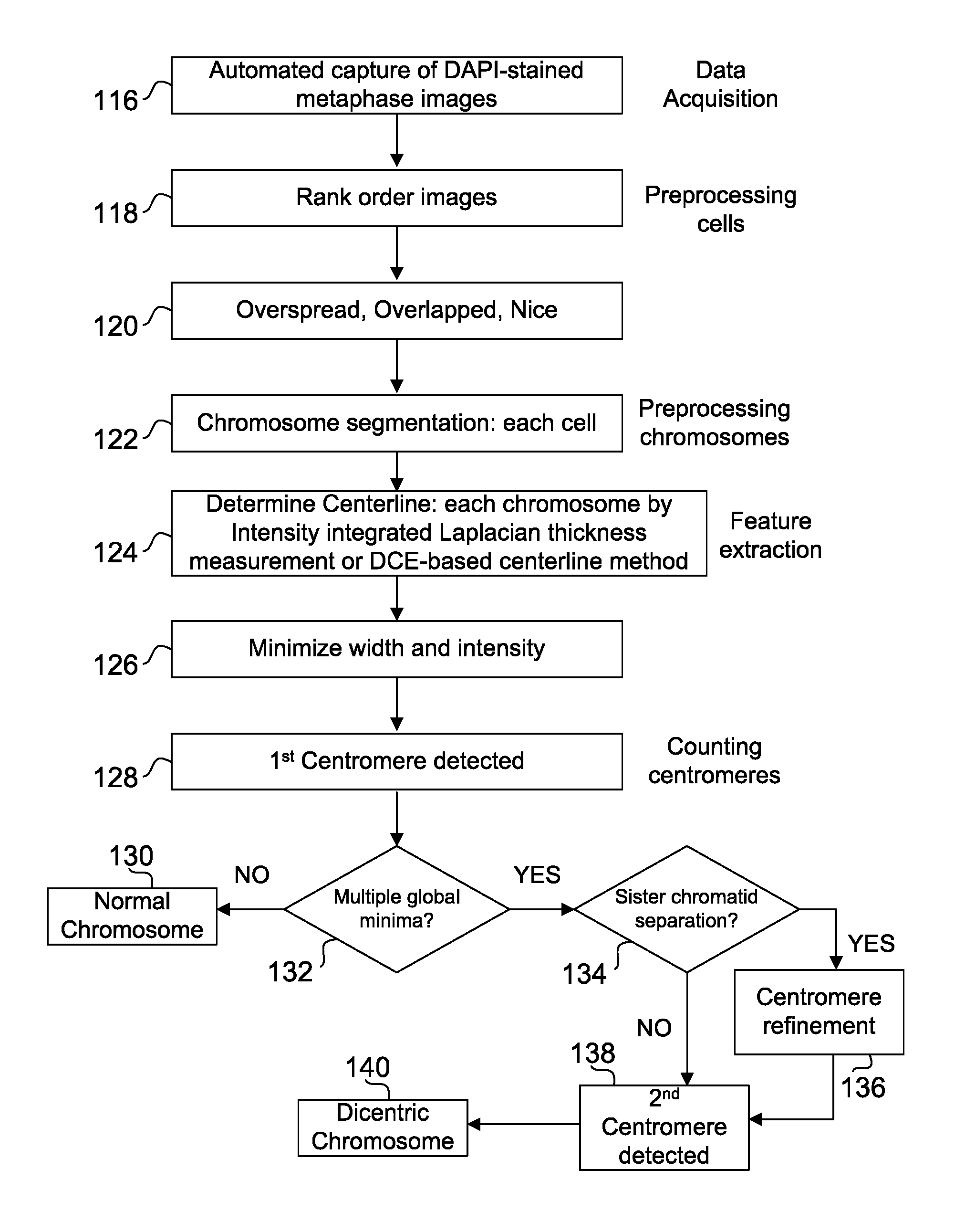
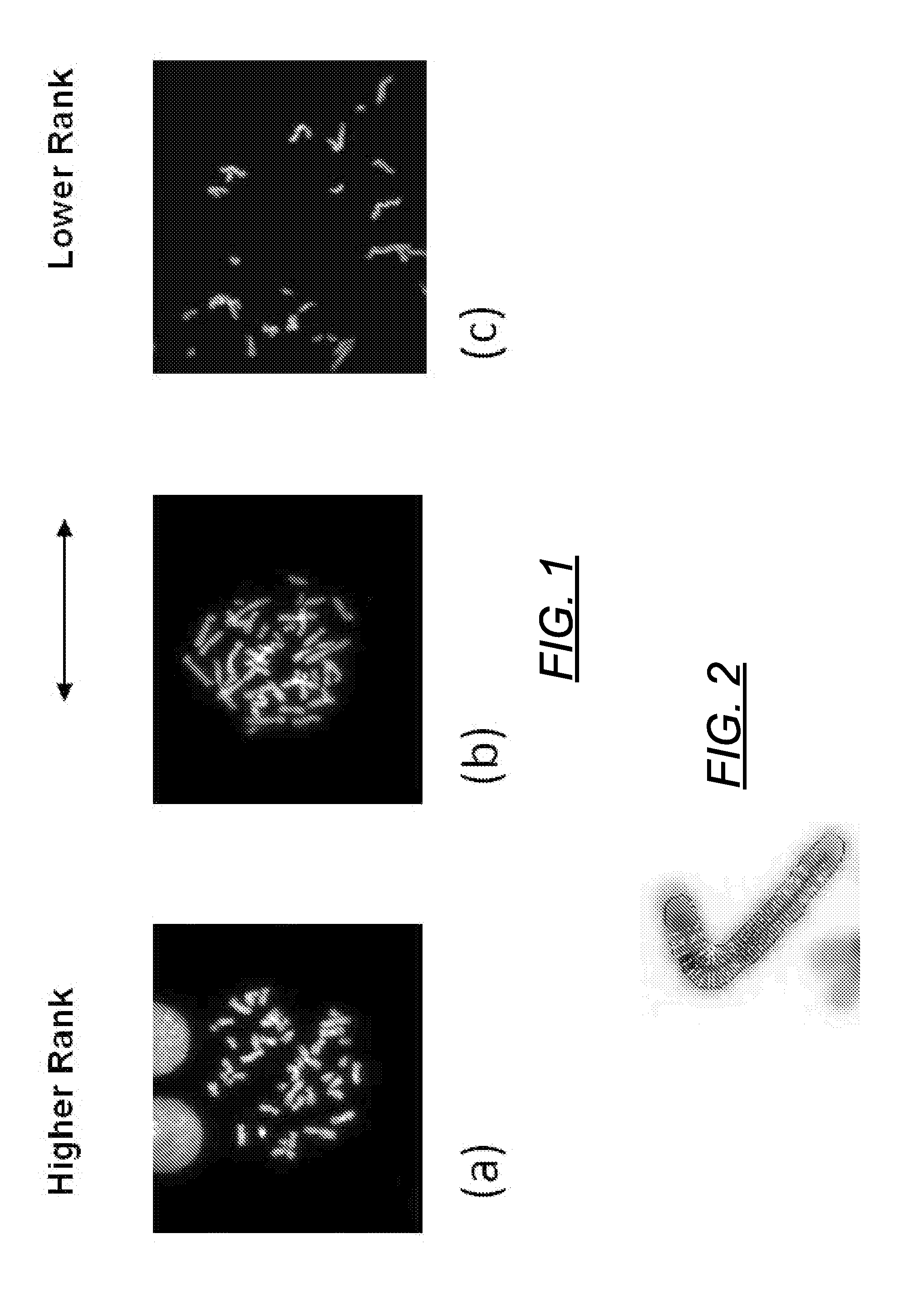
[0154]Cells from three different normal individuals were imaged by fluorescent microscopy after heat denaturing fixed metaphase chromosomes in 2×SSC, 50% formamide, 10% dextran sulfate solution and staining with DAPI (as described in J. Knoll and P. Lichter, Unit 4.3, Current Protocols in Human Genetics, Wiley NY, 1994, revised 2006). Grayscale images were obtained with a DAPI filter set using an Olympus BX61 microscope and Cytovision Software (Genetix Inc, San Joe, Calif.) and inverted. Denaturation enhances staining of centromeric and heterochromatic sequences (in contrast with single copy euchromatic domains) because of the preference of this dye for binding to double stranded A / T rich DNA which reforms due to self-renaturation of tandem alphoid monomers in these regions. Digitally captured images were then inverted, and partial metaphase regions containing well separated chromosomes were segmented to obtain their...

example 2

Results of Centromere Detection Algorithm for Dicentric Detection

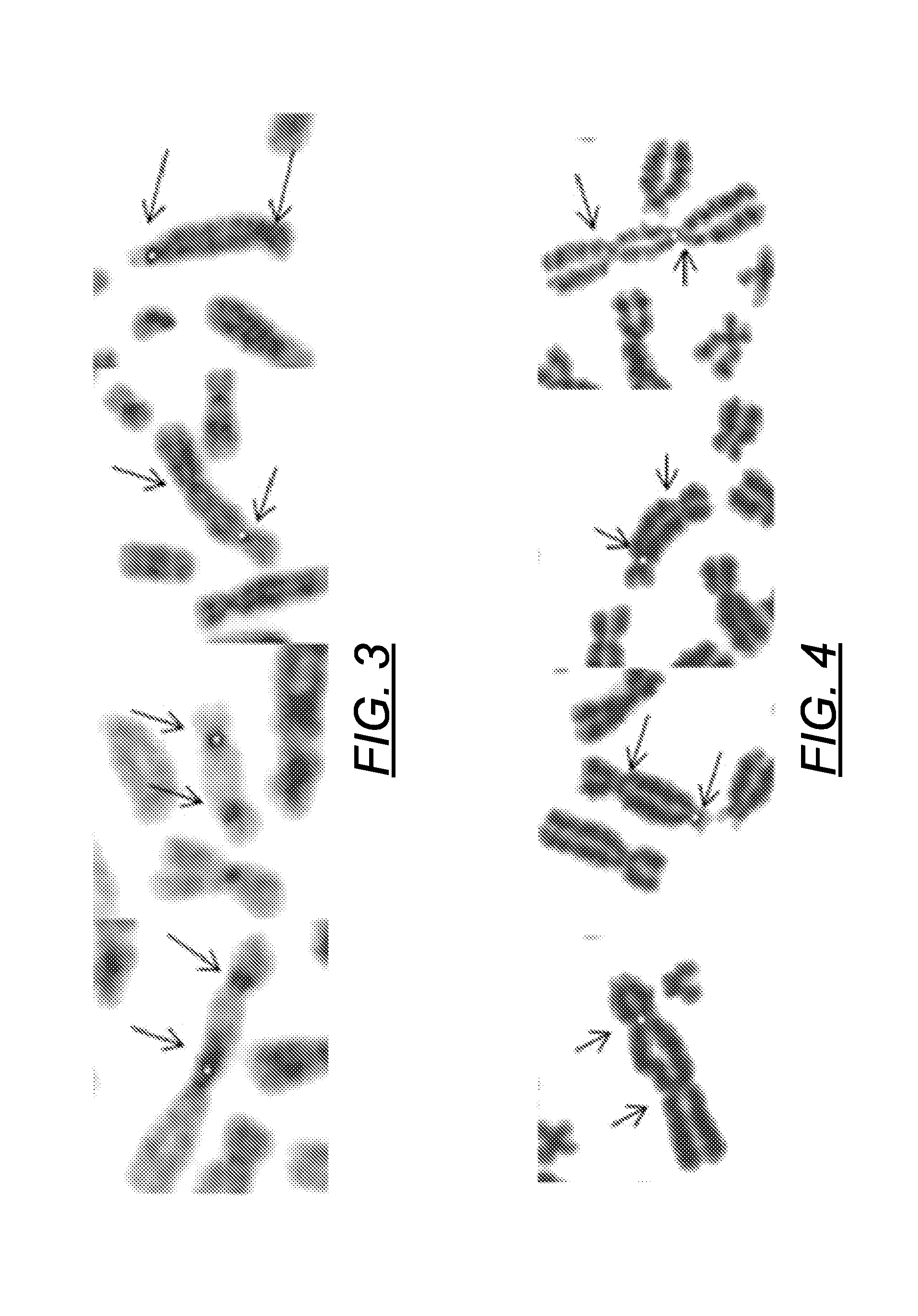
[0156]The algorithm was developed and tested on DAPI-stained irradiated metaphase chromosome images, and then adapted for FPG stained images. Metaphase spreads from cells were irradiated with 5 Gy of ionizing radiation by Dr. Ruth Wilkins (Health Canada; HC), then heat denatured, and stained with DAPI at Univ. Western Ontario (UWO). We then identified DCC manually and applied a modification of our published algorithm to detect centromeres (Subasinghe A et al. Canadian Conf. on Computer &Robot Vision, pp 223-230, DOI: 10.1109 / CRV.2010.36, 2010). After segmenting the chromosome and computing the centerline according to the method described infra, the software determines the centromere and the associated CCF values. The first centromere is then masked, and the process is repeated to find the second one. Typical examples of the two centromeres found by the algorithm are marked in FIGS. 3 and 4. Of 20 DCC, 17 (85%) have bot...


PUM

PropertyMeasurementUnit
angleaaaaaaaaaa
sizeaaaaaaaaaa
widthaaaaaaaaaa

Abstract

A method for determining radiation exposure from chromosome abnormalities present in a specimen by determining the location or locations of the centromere of each chromosome in a cell in an image of a metaphase cell by segmentation of an accurately drawn chromosome centerline followed by selection of a longitudinal cross-section with the minimum width or intensity or width and intensity; counting the number of centromeres in each chromosome in each cell; computing the frequency of dicentric chromosomes in a population of cells; and determining the radiation dose by comparing the computed frequency of dicentric chromosomes with a previously determined dose-response curve from a calibrated source.

Description

PRIORITY AND RELATED APPLICATIONS[0001]U.S. Ser. No. 61 / 410,849 filed Nov. 5, 2010; PCT / US2011 / 059257 filed Nov. 4, 2011.BACKGROUND OF THE INVENTION[0002]1. The Field of the Invention[0003]The present method relates to determining radiation exposure, more specifically, to a method for analyzing chromosome damage in cells that have been exposed to ionizing radiation by analyzing images of their centromere.[0004]2. Background Art[0005]Chromosome testing of blood through microscopy and manual scoring are presently the gold standards for evaluating human radiation exposures. (Blakely W F, et al. Health Phys. 89:494-504, 2005). However, these techniques presented problems with obtaining an accurate throughput. In these well known methods, blood cell cultures are first analyzed by Giemsa or Bromodeoxyuridine / Hoechst 33258 / Giemsa (Fluorescence plus Giemsa; FPG). This results in the staining of the chromosome during its metaphase stage. The stain spreads to determine the frequencies of the ...

Claims


Application Information

Patent Timeline
Patent Type & Authority Patents(United States)
IPC IPC(8): G06F19/16C12Q1/6883
CPCC12Q1/6883G06F19/16G16B15/00
Inventor ROGAN, PETER KEITHKNOLL, JOAN HELENSAMARABANDU, JAGATHSUBASINGHE, AKILA
Owner CYTOGNOMIX
Why Eureka
Try Eureka