Neural stimulation devices and systems for treatment of chronic inflammation

a technology of neurostimulation and system, applied in the field of chronic inflammation treatment systems and devices, can solve the problems of difficult and/or time-consuming system placement, difficult to stably position such devices in the proper position with respect to the nerve, and easy mechanical damage, so as to reduce communication errors and reduce magnetic afield absorption

Active Publication Date: 2013-12-17
SETPOINT MEDICAL CORP
View PDF524 Cites 211 Cited by
  • Summary
  • Abstract
  • Description
  • Claims
  • Application Information

AI Technical Summary

Benefits of technology

[0015]The POD cuff electrode configuration of the stimulation device may allow the device to be stably positioned proximate a nerve, such as the vagus nerve. Furthermore, the cuff electrode configuration may also have the characteristics of driving most of the current into the nerve, while shielding surrounding tissues from unwanted stimulation.
[0052]Any appropriate resonator may be used with the microstimulator. For example, the resonator may be a coil and capacitor configured to resonate at about 131 KHz+ / −2%. The resonator may comprise a ferrite coil wherein the ferromagnetic material is chosen to maximize permittivity in the operating range and minimize permittivity and energy absorption from higher frequency sources such as MRI and Diathermy devices.

Problems solved by technology

However, these systems can be difficult and / or time consuming to implant, as the electrodes and the IPG are usually implanted in separate areas and therefore the lead must be tunneled through body tissue to connect the IPG to the electrodes.
Also, leads are susceptible to mechanical damage over time, particularly as they are usually thin and long.
Unfortunately, the currently developed leadless devices tend to be larger and more massive than desirable, and even than traditional electrode / lead assemblies, making it difficult to stably position such devices in the proper position with respect to the nerve.
Without device stability, the nerve and / or surrounding muscle or tissue can be damaged due to movement of the assembly.
Further these devices require long charging times, and are often difficult to control (e.g., program) and regulate.
Current flows induced by non-shielded electrodes will vary in most situations with movements (e.g. neck movement, etc.) making control of the relationship with the target (and therefore reliable stimulation of the target) all but impossible.
However, for most situations, the target neuron is surrounded by tissues that are susceptible to unintended stimulation.
While convenient to implant, these unshielded microstimulators are unacceptable for most applications.

Method used


Image

  • Neural stimulation devices and systems for treatment of chronic inflammation
  • Neural stimulation devices and systems for treatment of chronic inflammation
  • Neural stimulation devices and systems for treatment of chronic inflammation

Examples


example 1

Microstimulator

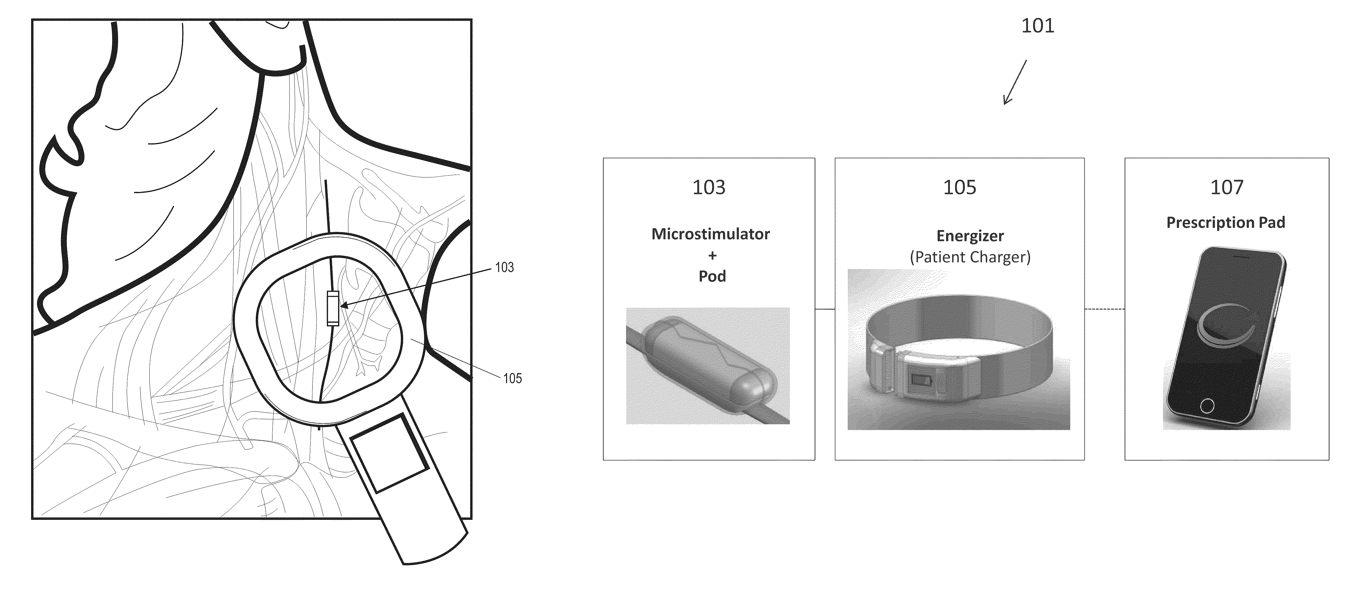
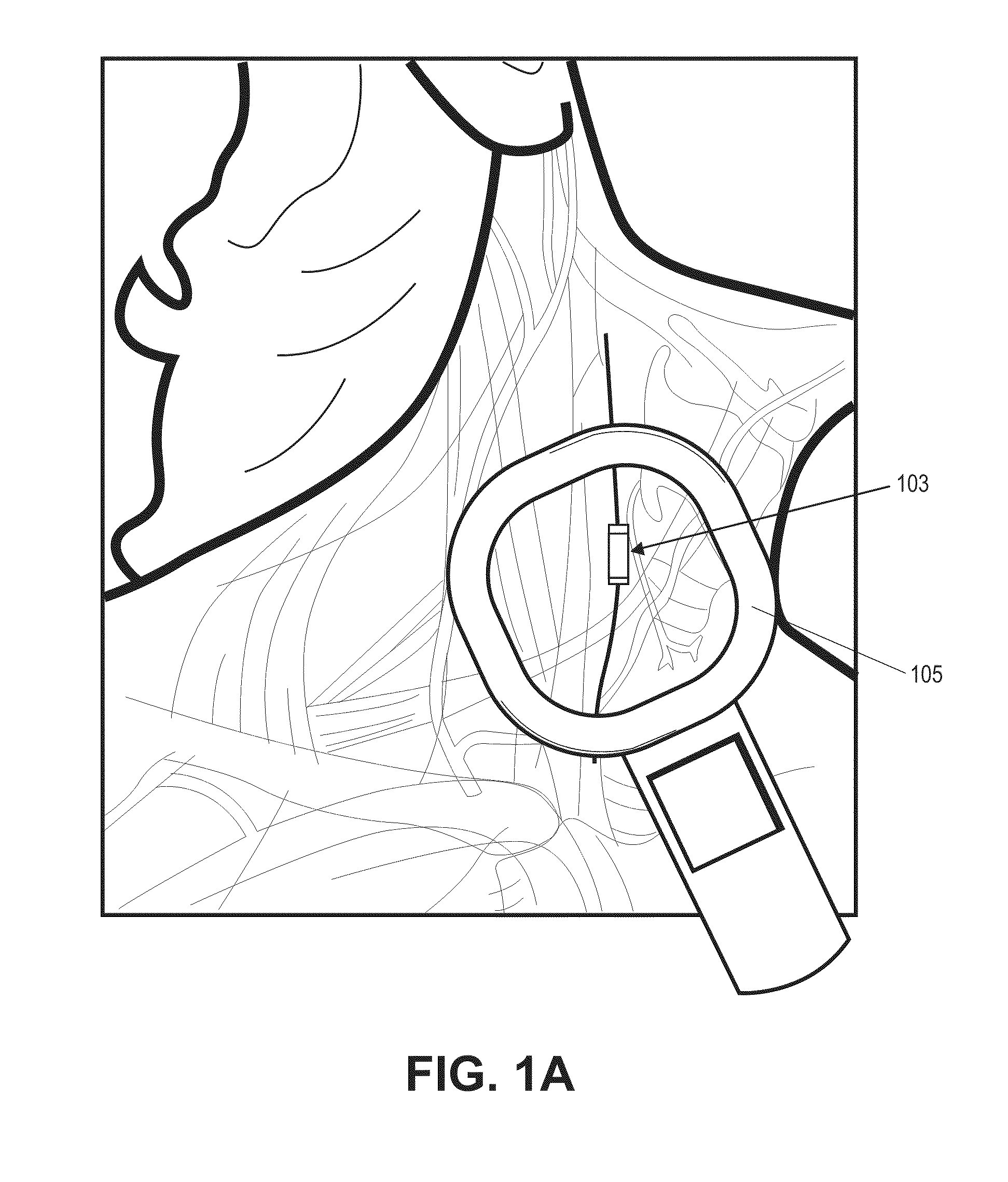
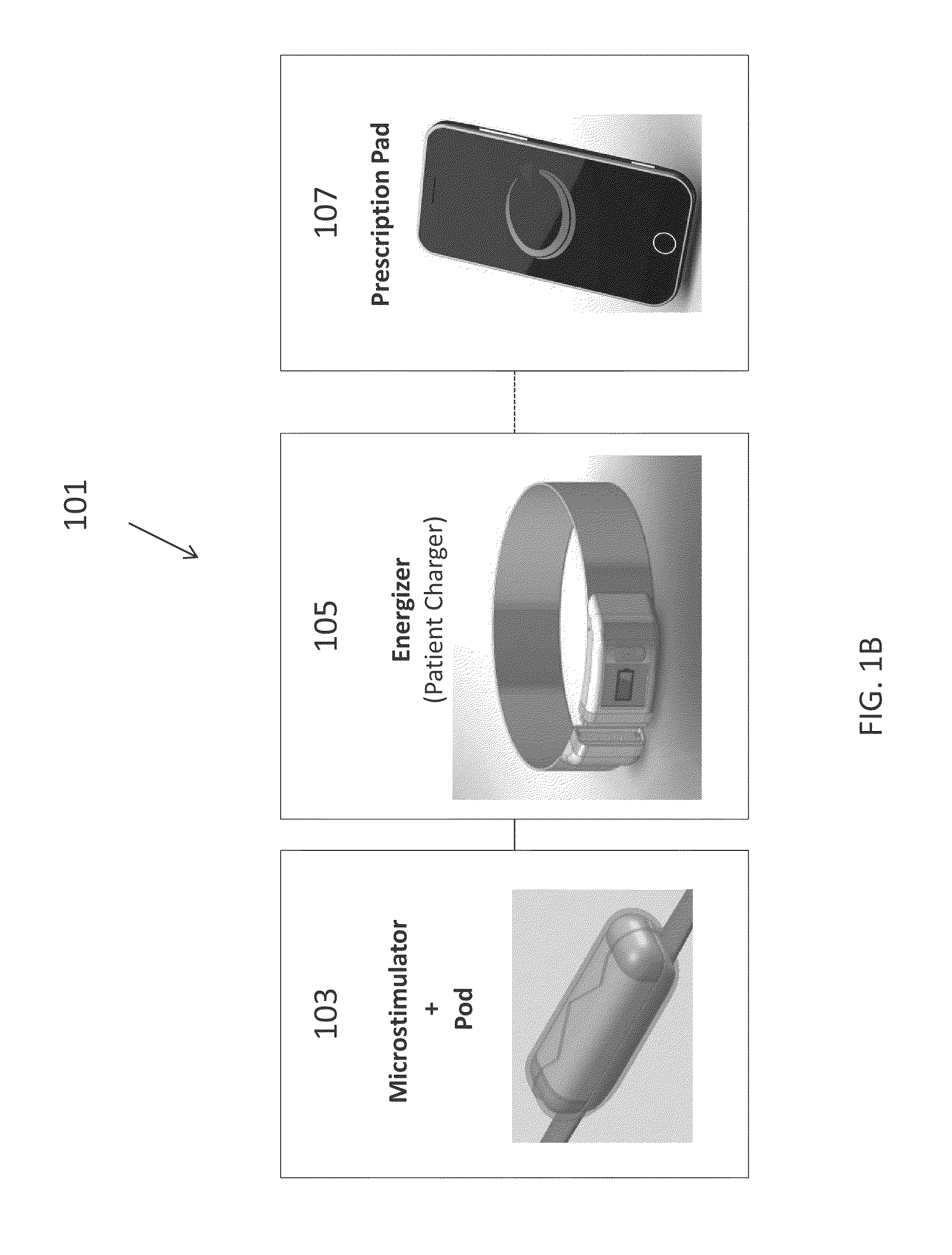
[0188]In this example, the microstimulator is a rechargeable neural stimulator that attaches to the vagus nerve and delivers current through bipolar platinum contacts against the nerve, as illustrated in FIG. 1B (103). The microstimulator battery may be charged by an external charger (“energizer”) and the energizer also functions as the communication gateway for the external controller (“prescription pad”). The Microstimulator in this example is physically housed in a rigid hermetic capsule with an attached electrode saddle. The hermetic capsule in this example is composed of an Alumina toughened Zirconia tube with metal ends brazed onto the ceramic tube. Brazing joints may use a nickel diffusion process or gold braze. The metal ends are an alloy of Titanium to reduce electrical conductivity and increase braze-ability. As shown in FIG. 23A, within the hermetic capsule is a resonator, hybrid with attached electronic parts, and batteries. The hybrid assembly is suspende...

example 2

Charger

[0275]One variation of a charger (referred to herein as an “energizer”) is described in FIGS. 36-43. In this example, the energizer for powering and programming the microstimulator attaches around the patient's neck like a necklace or collar. FIG. 36A shows one variation of the energizer around the subject's neck. In this example, about an average of 20 seconds of charging will be required per day for NCAP treatment using an implant as described above, and it is recommended that the patient charges at least every week (e.g., for approximately 20*7=3 minutes), even though it is possible not to charge for up to a month requiring a 20-30 minutes to charge.

[0276]In this example, the Energizer consists of 4 components: Coil and Magnetic Coil Connector Assembly, Electronic Module, Battery Module, and Acoustic Module.

[0277]FIG. 37 shows one variation of a coil and magnetic connector assembly. In this example, the Coil is 13 Turns of a bundle of 26 gauge magnet wire (N conductors) sp...


PUM


Abstract

A system for treating chronic inflammation may include an implantable microstimulator, a wearable charger, and optionally an external controller. The implantable microstimulator may be implemented as a leadless neurostimulator implantable in communication with a cervical region of a vagus nerve. The microstimulator can address several types of stimulation including regular dose delivery. The wearable charger may be worn around the subject's neck to rapidly (<10 minutes per week) charge an implanted microstimulator. The external controller may be configured as a prescription pad that controls the dosing and activity of the microstimulator.

Description

CROSS-REFERENCE TO RELATED APPLICATIONS[0001]This patent application claims priority to U.S. provisional patent application Ser. Nos. 61 / 289,946, titled “LEADLESS CUFF MICROSTIMULATOR STIMULATOR,” filed on Dec. 23, 2009; and 61 / 306,849, titled “NEURAL STIMULATION DEVICES AND SYSTEMS FOR TREATMENT OF CHRONIC INFLAMMATION,” filed on Feb. 22, 2010, each of which are herein incorporated by reference in their entirety.[0002]This patent application may also be related to abandoned U.S. patent application Ser. No. 12 / 874,171 (titled “PRESCRIPTION PAD FOR TREATMENT OF INFLAMMATORY DISORDERS”) and pending U.S. patent application Ser. No. 12 / 797,452 (titled “NERVE CUFF WITH POCKET FOR LEADLESS STIMULATOR”), each of which is herein incorporated by reference in its entirety.INCORPORATION BY REFERENCE[0003]All publications and patent applications mentioned in this specification are herein incorporated by reference in their entirety to the same extent as if each individual publication or patent a...

Claims


Application Information

Patent Timeline
Patent Type & Authority Patents(United States)
IPC IPC(8): A61N1/00
CPCA61N1/36053A61N1/37205A61N1/375A61N1/36142A61N1/3787A61N1/3606A61N1/36125A61N1/3756A61N1/36175A61N1/0556A61N1/37235
Inventor FALTYS, MICHAEL A.SIMON, JESSE M.LIU, YIMING
Owner SETPOINT MEDICAL CORP
Why Eureka
Try Eureka