Ion trap for cooling ions

a technology of ion traps and ion beams, which is applied in the field of ion traps, can solve the problems of limiting the minimum achievable emission of cooled ions, limiting the speed of operation, and limiting the gas emission rate of ions, so as to reduce the gas load of the analyser, save complexity and cost

Active Publication Date: 2014-02-04
THERMO FISHER SCI BREMEN
View PDF34 Cites 22 Cited by
  • Summary
  • Abstract
  • Description
  • Claims
  • Application Information

AI Technical Summary

Benefits of technology

[0012]Ions stored within the trap can thereby be cooled to a low temperature, and ejected from the trap into a mass analyser or into another device before mass analysis. This provides a significant degree of flexibility, since such ions can thereby be optimised for different types of mass analyser, including for instance, pulsed mass analysers. In contrast to prior art methods of gas jet cooling, it can be used with an ion beam that has undergone processing within the vacuum environment of the instrument, and not just for ion beams as they are introduced into the instrument.
[0013]All of the particles of a gas beam can be considered to have a vector of motion with a dominant component, the dominant component being common across all of the particles, such that the gas particles have a low divergence. As a result, the distribution of gas within the trap volume is non-uniform. Advantageously, the invention permits the efficient trapping and storage of ions in an ion trap with a much reduced bath gas pressure than normal as it has been found that the use of the directed beam of gas provides good ion storage and cooling capabilities due to sufficient collisions between the gas and the ions in the region of the beam. In this way, the ion trap of the invention may be operated at a lower pressure (i.e. away from the gas beam) than normally employed for ion traps which require the use of a large pressure of bath gas. Thus, the invention enables the gas load on the rest of the mass spectrometer system to be correspondingly reduced. Accordingly, the invention is preferably operated with a pressure in the ion trap (i.e. away from the beam) which on its own would be too low to store ions in the trap, especially to trap, store and cool ions. For example, whereas a typical pressure in an ion trap using bath gas may be about 1×10⁻³ mbar, the pressure in the ion trap according to the invention may be less than 1×10⁻⁴ mbar. Preferably, the pressure in the ion trap is about 1×10⁻⁴ mbar or less, more preferably less than 1×10⁻⁴ mbar, still more preferably about 5×10⁻⁵ mbar or less, e.g. in the region of 1×10⁻⁵ mbar. In a preferred embodiment, the method further comprises receiving ions at the trap.
[0031]Such modulation is preferably performed by a pulsed valve, to produce a series of gas plugs travelling through the trapping region. For example, this may allow cooling of ions when the gas plugs are transmitted, and extraction of the ions during the gap time between plugs. This may further reduce any interaction between ions and gas during the extraction process. In an embodiment, a further valve is located in the path along which the extracted ions travel. This valve is opened only to allow ions to travel towards the analyser. This reduces the gas load on the analyser from the trapping region and other regions outside the analyser, and may avoid the use of differential pumping, saving complexity and cost. The pulsed valve may comprise a piezoelectric or electromagnetic arrangement for example, and may operate in a pulsed manner or in a harmonically oscillating manner, synchronised to the injection of ions from the trapping region into the analyser.

Problems solved by technology

However, in such devices, the ions can only be cooled to the temperature of the gas, which is limited to that of the ion optics of the trap, since the gas is effectively held within the trap, in thermal equilibrium with the material with which it is trapped.
This places a limit on the minimum achievable emittance of the cooled ion beam.
Moreover, when the trap is used for injecting the cooled ions into the mass spectrometer, further problems arise.
Accelerating the ions through the gas can cause fragmentation of the ions and removing the gas before ejecting the ions limits the speed of operation significantly.
This turns prevention of gas carry-over into the analyser into a serious problem.
This problem is typically alleviated by avoiding line-of-sight between the trap and the analyser and by using small apertures, at the expense of increased cost and complexity and reduced performance.
Also, this further increases path length, thereby worsening any external mass separation problems.
However, such devices are not compatible with trapping, since they are designed to allow the cooled ions to be injected into the mass analyser immediately.
Furthermore, gas carry-over remains a problem with such devices.
Such ion traps additionally employ a significant pressure of bath gas in the trap for storage of the ions thus significantly adding to the gas load of the system.

Method used


Image

  • Ion trap for cooling ions
  • Ion trap for cooling ions
  • Ion trap for cooling ions

Examples


first embodiment

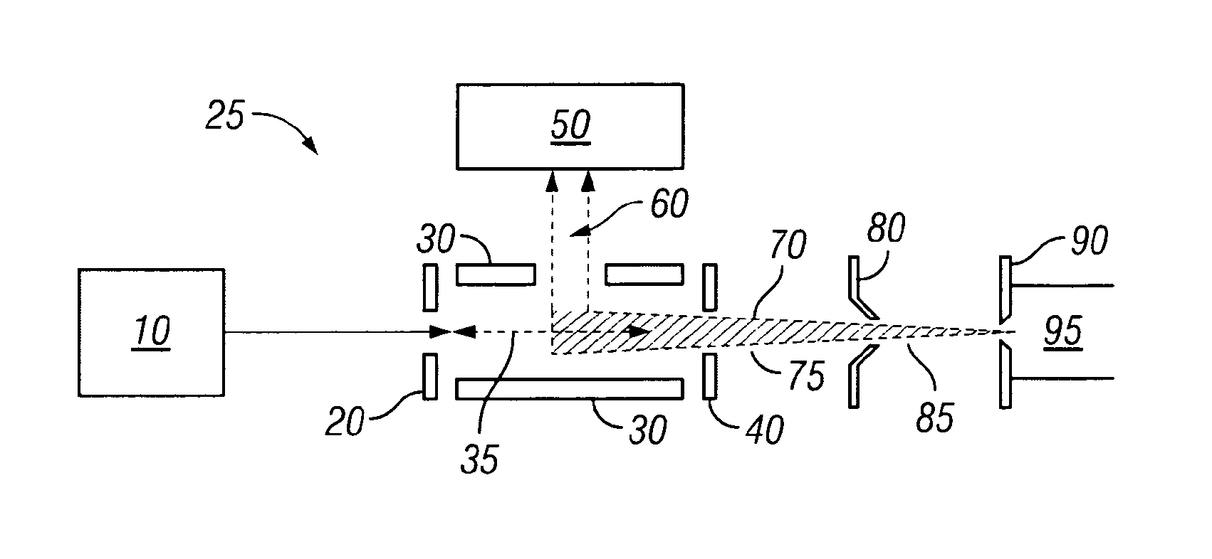
[0036]Referring first to FIG. 1, there is shown a mass spectrometer according to the invention. Ions are introduced from an ion source 10 through a first aperture 20 into an ion trap 25 defined by an extended set of rods 30, which are preferably quadrupolar. The rods 30 define a longitudinal axis 35, bounded by the first aperture 20 and a second aperture 40. Mass analyser 50 is provided adjacent the ion trap in a direction perpendicular to the longitudinal axis. An external gas line 95 is coupled to nozzle 90 and skimmer cone 80, adjacent to the nozzle, defines a differential pumping aperture.

[0037]An RF potential is applied to the rods 30 of the ion trap 25, such that the ions are directed along the longitudinal axis 35 of the ion trap. The ions are confined axially by voltages applied to first aperture 20 and second aperture 40. Gas enters the mass spectrometer from external gas line 95 through the nozzle 90 into a first pumping region 85. It thereby forms a gas jet 70 by superson...

second embodiment

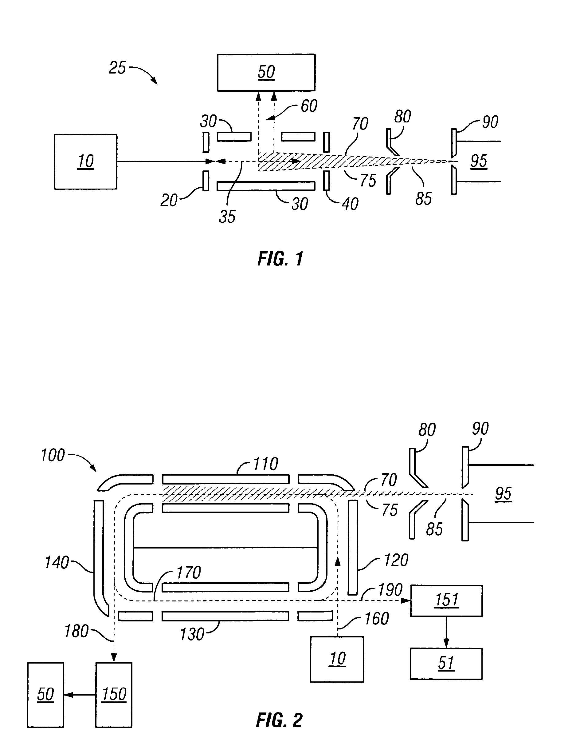
[0043]An implementation of this principle is illustrated in FIG. 2, in which there is shown a mass spectrometer according to the present invention. Where the same features are shown as in FIG. 1, identical reference numerals are used. An ion trap 100 is formed in a race-track shape, comprising a first segment 110, second segment 120, third segment 130 and fourth segment 140.

[0044]Ions generated in ion source 10 are directed towards the ion trap 100. The potential applied to segment 120 of the ion trap 100 is switched off, for example, for several tens microseconds, to allow ions to arrive. Injected ions move along the circumference of ion trap 100. Gas jet 70 is generated through nozzle 90 and skimmer cone 80 and thereby directed towards segment 110. The ions trapped in the ion trap 100 periodically pass through the gas jet 70 and become more and more equilibrated with gas molecules, both in speed and temperature. It will be appreciated that directing of the beam through the trappin...

third embodiment

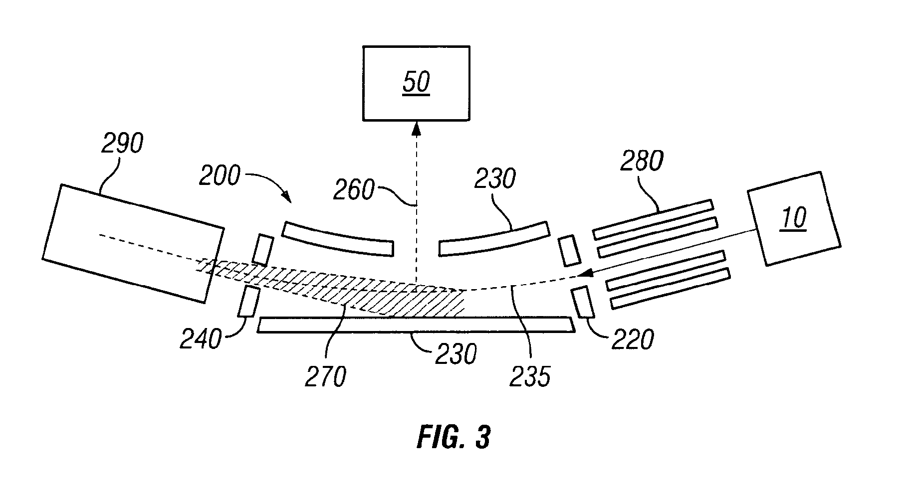
[0048]Referring to FIG. 3, there is shown a third embodiment according to the present invention. Where the same features are shown as in FIGS. 1 and 2, identical reference numerals are used. An ion trap 200 is provided which is of a C-trap form, as described e.g. in WO 2008 / 081334, defined by elongate electrodes 230 at least some of which are curved along their long axis. The elongate electrodes 230 define a long axis 235 of the trapping region which is thus slightly curved. A mass analyser 50 is provided adjacent the C-trap 200 in a direction orthogonal to the long axis 235 of the trapping region. The C-trap 200, like the ion trap 25 of FIG. 1, is open to its surroundings, which is not typical for ion traps which are normally operated at elevated pressure compared to their surroundings, the elevated pressure being maintained by an enclosure and a supply of collision gas. Instead the C-trap 200 is operated with a low internal pressure in the trap of typically about 1×10⁻⁴ mbar or le...


PUM


Abstract

A method of changing the kinetic energy of ions is provided, comprising: trapping ions in a trapping region of an ion trap; and directing a beam of gas through the trapping region, so as to change the kinetic energy of the trapped ions thereby. Also provided is a method of separating ions, the method comprising: causing ions to enter a trapping region of an ion trap along a first axis of the trapping region; directing a beam of gas along the first axis and applying an electric potential in the direction of the first axis so as to cause separation of the ions based on their ion mobility. An ion trap and a mass spectrometer for performing the methods are also provided.

Description

TECHNICAL FIELD[0001]This invention relates to an ion trap for changing the kinetic energy of ions and a method of changing the kinetic energy of ions in an ion trap, preferably to cool the ions.BACKGROUND TO THE INVENTION[0002]For high resolution mass spectrometers, it is desirable that ions for analysis have a low emittance, since this improves resolving power and sensitivity. The ion beam emittance is in part determined by its temperature. Traditionally, ions are cooled by collisions with a gas. However, since the mass analyser operates at a high vacuum, it is desirable to cool the ions outside of the mass analyser.[0003]Existing solutions have followed two divergent strategies. A first strategy is to cool the ions in a trap, external to the mass analyser, which contains a gas suitable for cooling the ions, for example as shown in U.S. Pat. No. 6,674,071. However, in such devices, the ions can only be cooled to the temperature of the gas, which is limited to that of the ion optic...

Claims


Application Information

Patent Timeline
Patent Type & Authority Patents(United States)
IPC IPC(8): B01D59/44
CPCG01N27/622H01J49/0481H01J49/004H01J49/422H01J49/02
Inventor MAKAROV, ALEXANDER A.DENISOV, EDUARD V.
Owner THERMO FISHER SCI BREMEN
Why Eureka
Try Eureka