Heat conduction-type sensor for calibrating effects of temperature and type of fluid, and thermal flow sensor and thermal barometric sensor using this sensor

a technology conduction-type sensor, applied in the direction of heat measurement, fluid pressure measurement by thermal means, instruments, etc., can solve the problems of inability to measure fine temperature differences, inability to accurately calibrate the effect of temperature and type of fluid, and the cost of flow sensors is too high, etc., to achieve small and inexpensive thermal flow sensors, easy to form, and reduce the effect of effects

Inactive Publication Date: 2014-03-11
GAKUIN TOHOKU
View PDF2 Cites 75 Cited by
  • Summary
  • Abstract
  • Description
  • Claims
  • Application Information

AI Technical Summary

Benefits of technology

[0064]The heat conduction-type sensor according to the present invention comprises at least two thin films, i.e., a thin films 10 (having a thin-film heater and a temperature sensor mounted thereon) thermally separated from a substrate and a thin film 12 (having a temperature sensor mounted thereon) under specified conditions such as a heating temperature of a predetermined heater, electric power, and others, these thin films are arranged in proximity to each other to exchange heat only through a measurement target fluid, and hence this sensor has an advantage that effects of a type and a temperature of the measurement target fluid can be automatically calibrated to indicate a flow velocity or a mass flow detected by the thermal flow sensor and an atmospheric pressure detected by the thermal barometric sensor by comparing data (information) concerning a heat transfer coefficient previously measured using a standard gas under the same conditions and data concerning a heat transfer coefficient of the unknown measurement target fluid.
[0065]An amplification circuit, an arithmetic circuit, or a control circuit which is a primary element as calibration circuit means 200 configured to eliminate effects of a temperature and a type of the measurement target fluid can be incorporated in a semiconductor sensor chip of the heat conduction-type sensor, thereby performing automatic calibration. Furthermore, electrode pads such as an electrode pad of the heater 25 provided on the semiconductor sensor chip, an electrode pad of the temperature sensor 20, an electrode pad of an absolute temperature sensor for measuring an absolute temperature of the substrate 1, and others can be wired to a package having the semiconductor sensor chip mounted thereon by wire bonding or the like without incorporating the calibration circuit means 200 in the semiconductor chip, and the calibration circuit means 200, e.g., the arithmetic circuit or the control circuit can be provided in the packaged heat conduction-type sensor. Moreover, the calibration circuit means 200 may be formed outside the heat conduction-type sensor. In this case, a terminal for the calibration circuit means is fabricated in the heat conduction-type sensor in advance to enable communication with the calibration circuit means provided outside through this terminal. In this manner, since the very compact heat conduction-type sensor can be manufactured, there can be obtained an advantage that the compact thermal flow sensor or thermal barometric sensor that can automatically calibrate effects of a temperature and type of the measurement target fluid can be provided.
[0066]Since the heat conduction-type sensor according to the present invention uses the thin-film thermocouple 120 as the temperature sensor 20, it is preferable for measuring a temperature rise of the thin film 10 or the thin film 12 when heated by the heater.
[0067]In the heat conduction-type sensor according to the present invention, since the thin film 10, the thin film 12, the thin film 11, and the coupling thin film 13 are formed of the SOI layer, utilizing single-crystal properties of this layer enables easily forming a diode, a transistor, a thin-film thermocouple, a resistive element, and others in this region, and hence there can be obtained an advantage that an integrated circuit can be formed or a thin film floating in midair can be readily formed by utilizing a difference in etchant between a buried insulator layer (a BOX layer) and the SOI layer.
[0068]The thermal flow sensor according to the present invention has a configuration that the thin film 10 thermally separated from the substrate includes the heater 25, the thin film 11 including the thin-film thermocouple 120 is arranged in proximity to the thin film 10, and a region of the hot junction 81 of the thin-film thermocouple 120 is coupled with the maximum temperature region 85 of the thin film 10 through the coupling thin film 13 having thermal resistance. Therefore, since the coupling thin film 13 has a heat transfer coefficient sufficiently higher than a heat transfer coefficient of the measurement target fluid such as a gas or a liquid, a type of the measurement target fluid or the heat transfer ratio having temperature dependence can be substantially ignored. In particular, if correction (calibration) of an ambient temperature can be ignored or the correction is required, its effects can be greatly lessened, and the calibration circuit means constituted of a simple calibration circuit can suffice, thereby obtaining an advantage that the small and inexpensive thermal flow sensor can be provided.
[0069]The thermal flow sensor according to the present invention has an advantage that a degree of thermal resistance of the coupling thin film 13 as a thermal resistance region 47 can be adjusted by adjusting a width, a length, or a thickness of this thin film or by selecting a material of the same as required.

Problems solved by technology

Therefore, for example, since two absolute temperature sensors must be prepared in order to measure a temperature difference and a difference between outputs from these sensors must be obtained, this method is inappropriate to measure a fine temperature difference because of a large error.
Therefore, since a variation with time is large and effects of an ambient temperature are reflected as they are since this sensor is an absolute temperature sensor, correcting the ambient temperature is difficult, many sensors and a temperature control system using these sensors are required to enable this correction, and the flow sensor necessarily becomes expensive.
However, there is a problem that a heat transfer coefficient of the fluid varies when a temperature of the surrounding fluid changes and, although the thermocouples as temperature difference sensors are provided as the temperature sensor, a temperature difference output differs due to a fluctuation of temperature of the fluid itself even when the heater is heated with the same power or the same is heated while controlling to provide a temperature difference from the same substrate because of temperature dependence of the heat transfer coefficient of the fluid, thereby complicating temperature correction.
Of course, when a type of the fluid is changed, its heat transfer coefficient differs, and hence there is a problem that effects of the type of the fluid are also considerable.
However, these examples have a problem that a region of the sensor portions is necessarily increased since the thermopile is used to amplify a temperature difference output, a diaphragm structure must be provided to increase a junction area with respect to the substrate in order to form many cold junctions, whereby heat from the heater flows to the substrate side to reduce the temperature and a temperature sensor region has a temperature distribution.
In particular, when using thermocouples as a temperature sensor, there is a problem that heat that moves along the flow of the fluid is conducted to the substrate side in the flow direction to facilitate cooling and a position of a peak in the temperature distribution may possibly get across a position of a hot junction of the thermocouples.

Method used


Image

  • Heat conduction-type sensor for calibrating effects of temperature and type of fluid, and thermal flow sensor and thermal barometric sensor using this sensor
  • Heat conduction-type sensor for calibrating effects of temperature and type of fluid, and thermal flow sensor and thermal barometric sensor using this sensor
  • Heat conduction-type sensor for calibrating effects of temperature and type of fluid, and thermal flow sensor and thermal barometric sensor using this sensor

Examples


example 1

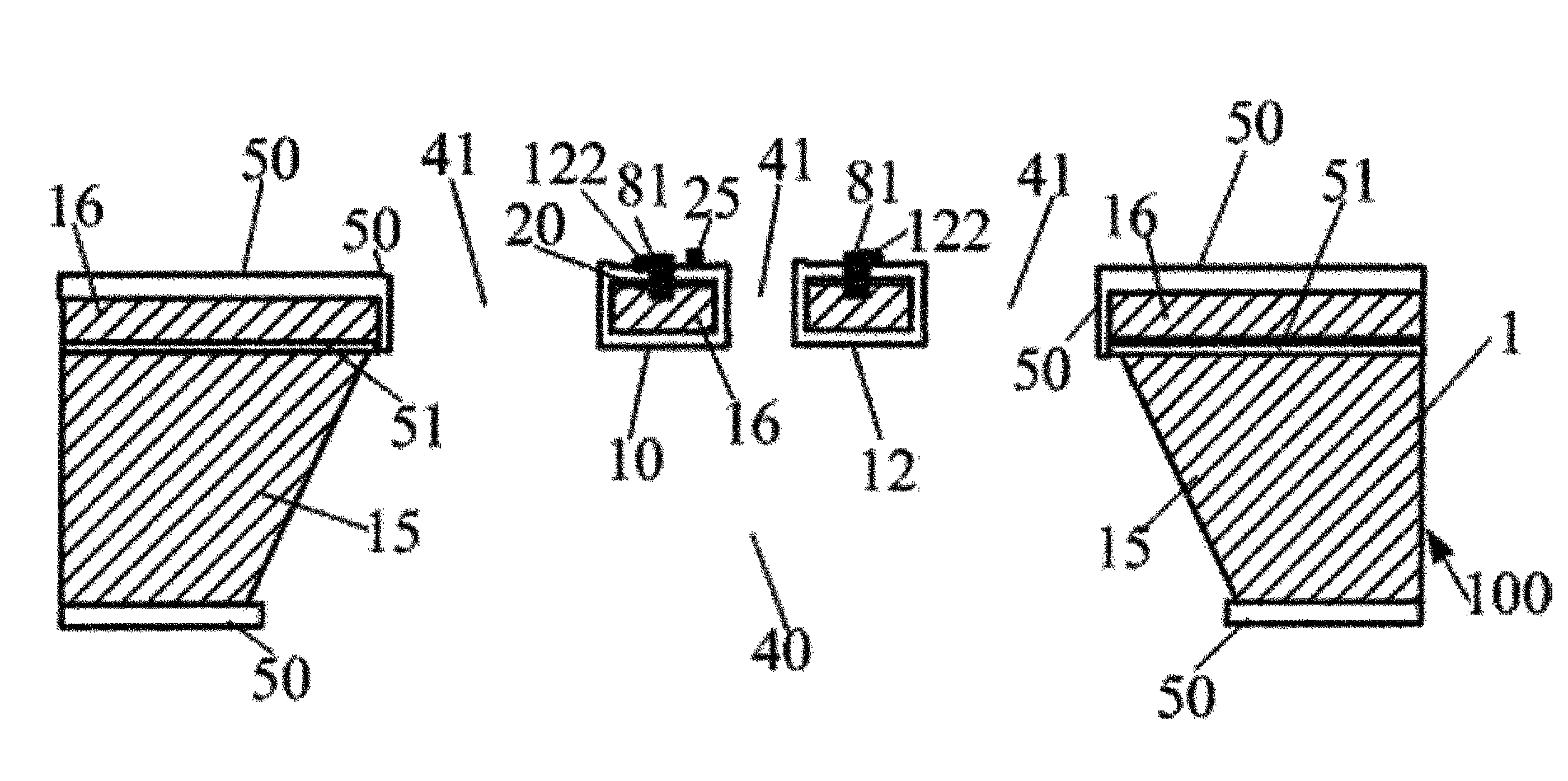
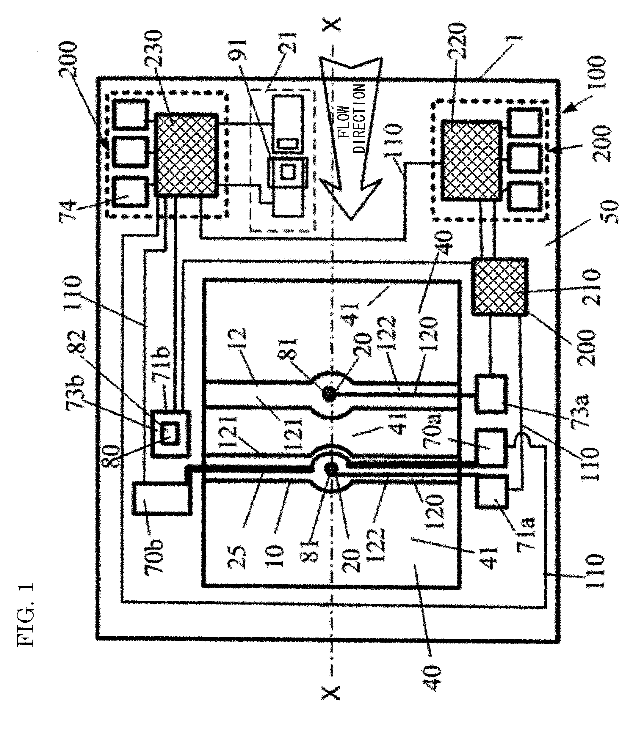
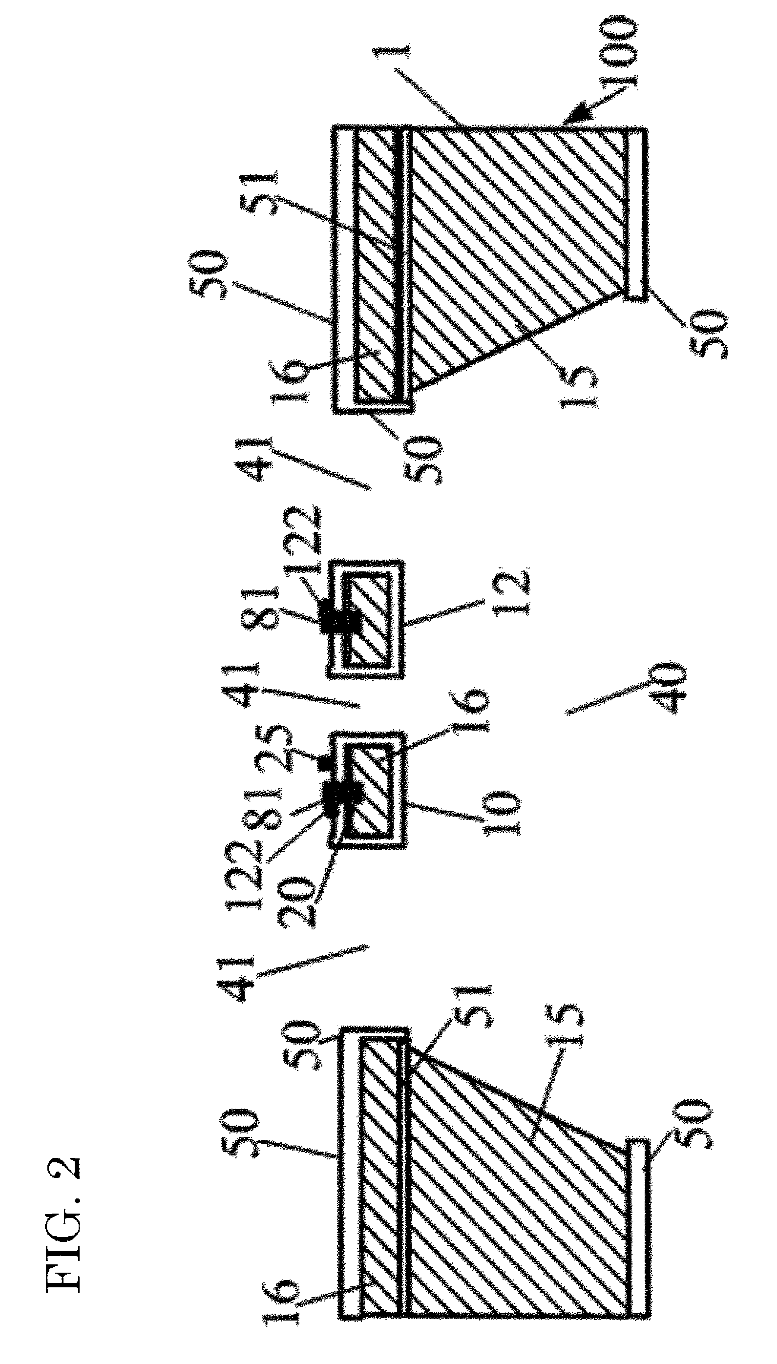
[0139]FIG. 1 is a plan schematic view of a sensor chip showing an example of a heat conduction-type sensor according to the present invention, and FIG. 2 is a cross-sectional schematic view taken along a cross section X-X. In this example, a semiconductor silicon substrate 1 is used as a heat conduction-type sensor according to the present invention, and there is shown an example that an amplifier 210, an arithmetic circuit 220, and a control circuit 230 which are primary parts as calibration circuit means 200 for calibrating effects of a type or a temperature of a measurement target fluid are formed and provided on this substrate 1. Further, this is a situation where an SOI substrate as the substrate 1 is used and applied to a thermal flow sensor but it can be likewise embodied as a thermal barometric sensor as it is.

[0140]In the SOI substrate as the substrate 1, since a BOX layer 51 as a buried insulating layer is present below an SOI layer 16, the SOI layer 16 or an underlying su...

example 2

[0149]The heat conduction-type sensor chip 100 shown in FIG. 1 and FIG. 2 in the foregoing example can be used and embodied as a simple thermal barometric sensor. A description will be given as to an example that the heat conduction-type sensor depicted in FIG. 1 and FIG. 2 of the present invention is embodied as the thermal barometric sensor. In the thermal barometric sensor, as different from the application to the thermal flow sensor in Example 1, even if a measurement target fluid has no flow or if it has a flow, a mesh cover or the like is directly disposed to a thin film 10 and a thin film 12 as sensing portions of a sensor chip so that an air current cannot reach these films, and measurement is carried out in a state that the flow is blocked. Therefore, when embodying this thermal barometric sensor, the above Expression 1 is applied. Further, a heat transfer coefficient h of a gas is a function of a type and a temperature Ta of the gas and an atmospheric pressure. First, a te...

example 3

[0152]FIG. 3 is a plan schematic view of a heat conduction-type sensor chip showing another example of the heat-conduction type sensor according to the present invention in which an amplifier 210, an arithmetic circuit 220, and a control circuit 230 as primary parts of a calibration circuit means 200 are provided outside rather than being formed on the heat conduction-type sensor chip 100, but instead respective electrode pads 70a, 70b, 71a, 71b, and others are provided on the heat conduction-type sensor chip 100 in such a manner that they can be also used as calibration circuit terminals 75 for the calibration circuit means 200 provided outside to enable supply / reception of power or communication with the calibration circuit means 200 provided outside. Further, as different from the example of the heat conduction-type sensor chip 100 depicted in FIG. 3, FIG. 4 shows that a thin film 12 is constituted of a cantilever 46 and has a hot junction 81 of a thin-film thermocouple 120 as a ...


PUM


Abstract

A heat conduction-type sensor corrects (calibrate) effects of a temperature of a measurement target fluid and a type of the fluid on a measurement value in measurement of a flow velocity, a mass flow, or an atmospheric pressure. Also provided is a thermal flow sensor and a thermal barometric sensor with this correcting function, high sensitivity, simple configuration, and low cost. At least two thin films that are thermally separated from a substrate through the same cavity are provided, one thin film comprises a heater and a temperature sensor, and the other thin film comprises at least one temperature sensor, the temperature sensors being thin-film thermocouples. The thin film is arranged in proximity so that it is heated only through the measurement target fluid by heating of the heater. A calibration circuit calculates and compares quantities concerning heat transfer coefficients of a standard fluid and the unknown measurement target fluid.

Description

TECHNICAL FIELD[0001]The present invention relates to a heat conduction-type sensor that measures a flow such as a mass flow or a flow velocity of a fluid as a gas or a liquid or measures a pressure of a gas. The present invention provides a thermal flow sensor and a thermal barometric sensor as small and inexpensive heat conduction-type sensors with a simplified structure and high sensitivity each of which is provided with a function for enabling automatic calibration of effects of a temperature and a type of a fluid even though this fluid is unknown, the heat conduction-type sensor being applied to the thermal flow sensor and the thermal barometric sensor and being capable calibrating the effects of temperature dependence or a type such as a gas type of a measurement target fluid based on information concerning a heat transfer coefficient or temperature dependence of the measurement target fluid.BACKGROUND ART[0002]The present applicant has invented an “electric heater” (Patent Do...

Claims


Application Information

Patent Timeline
Patent Type & Authority Patents(United States)
IPC IPC(8): G01F1/68
CPCG01L11/002G01L19/04G01F1/6842G01F1/692G01F1/6845G01F1/6965G01L27/002G01L19/0092
Inventor KIMURA, MITSUTERU
Owner GAKUIN TOHOKU
Why Eureka
Try Eureka