Systems and methods for structural sensing

a structural sensing and system technology, applied in the direction of structural/machine measurement, instruments, heat measurement, etc., can solve the problems of complex network of sensors and wires, poor spatial resolution, and inability to detect features within the bulk of the article being analyzed

Inactive Publication Date: 2014-04-01
MASSACHUSETTS INST OF TECH
View PDF45 Cites 12 Cited by
  • Summary
  • Abstract
  • Description
  • Claims
  • Application Information

AI Technical Summary

Problems solved by technology

Present SHM systems can have one or more drawbacks, including relatively poor spatial resolution, inability to detect features within the bulk of the article being analyzed, the need for complex networks of sensors and wires, high power requirements, high cost, and high noise, among others.

Method used


Image

  • Systems and methods for structural sensing
  • Systems and methods for structural sensing
  • Systems and methods for structural sensing

Examples


example 1

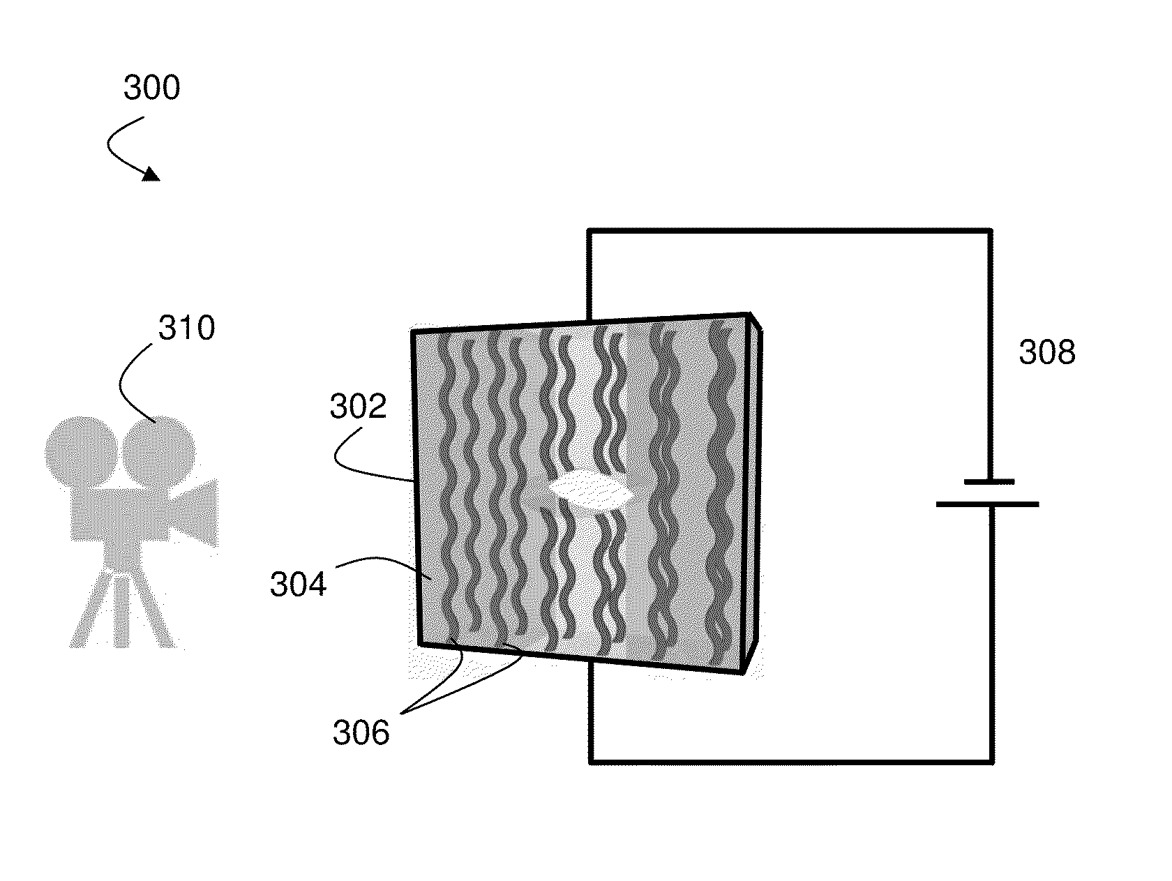
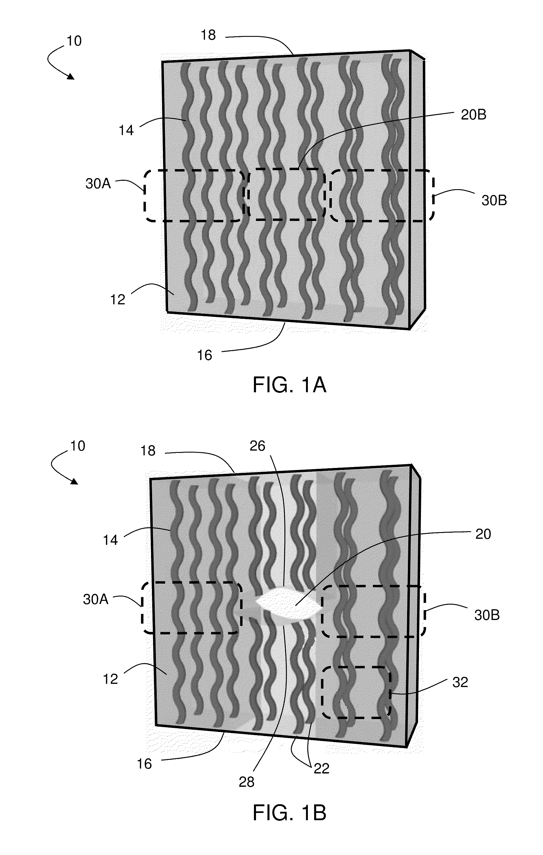
[0097]This example describes the determination of one or more mechanical characteristics in structural elements via resistive heating. In this example, a differential voltage was applied to a network of carbon nanotubes (CNTs). Defects within the network of CNTs produced a change in the local resistivity, and therefore in temperature, which was measured using a thermal camera.

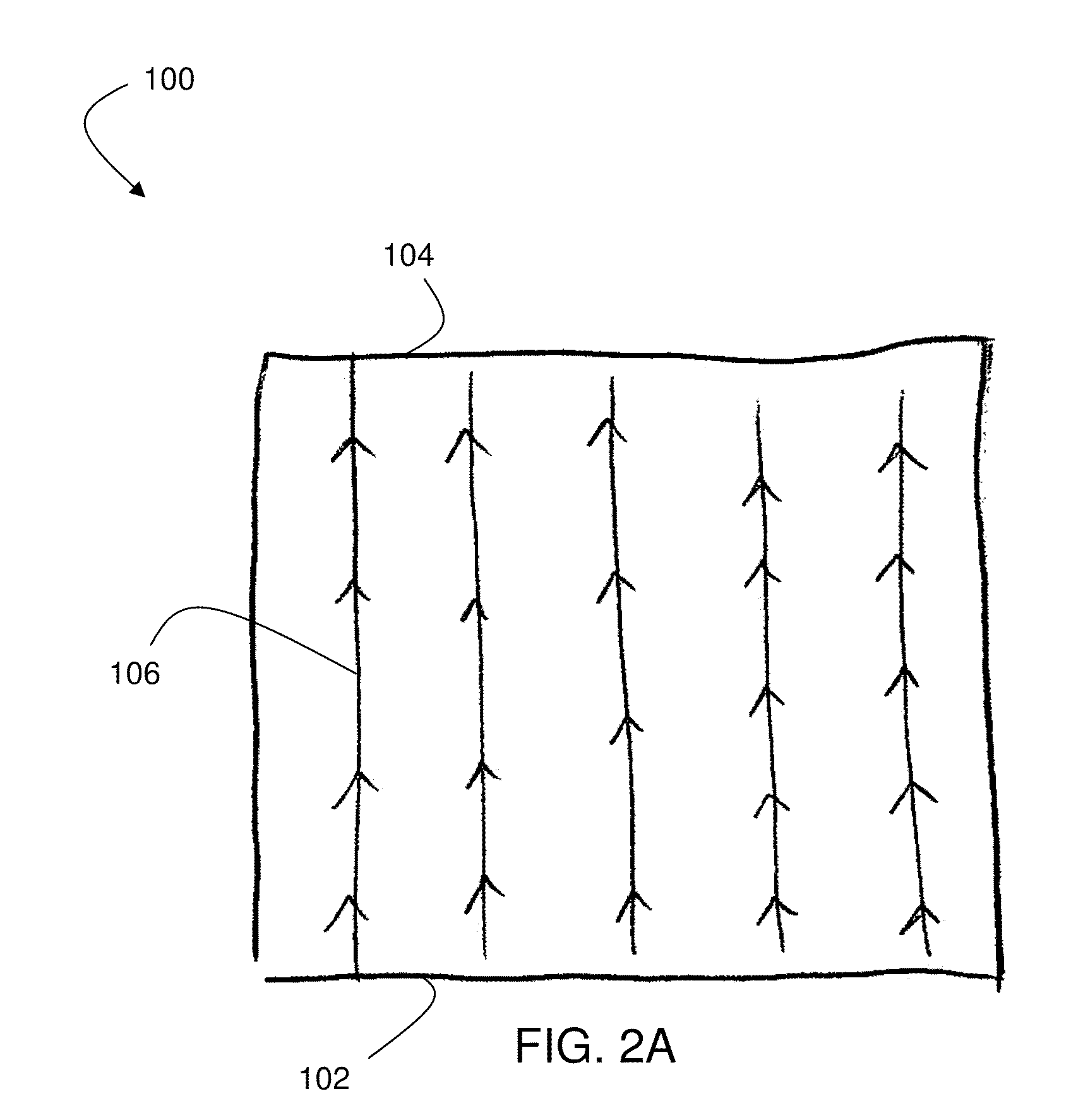
[0098]In this example, a vertically-aligned CNT forest was grown on a silicon wafer by placing the wafer in an atmospheric pressure quartz tube furnace (Lindberg). In order to grow CNTs, a Chemical Vapor Deposition process was used, flowing He, C2H4 and H2 during the different growth steps. The growth temperature was 650° C., as measured by thermocouples in the tube furnace. Aligned MWCNTs were grown uniformly on the surface of the silicon wafer, to produce a 6 cm×4 cm (VACNT) forest. The CNTs appeared to be distributed uniformly over the silicon wafer, with a few clear spots observable with the naked eye (as i...

example 2

[0102]In this example, the effect of the amount of electrical power imparted to a composite sample on the system temperature was investigated. A nano-engineered composite specimen comprising 3 plies of fuzzy fiber alumina cloth and cured epoxy resin was heated varying the intensity of the power supply, as shown in FIG. 6A. The composite specimens were made using a hand lay-up method. A woven cloth comprising alumina fibers and CNTs (made using the techniques described in Example 1) was placed on a metal sheet coated with a Teflon film. A commercial epoxy (Resin 105 and Hardener 206 from West Systems Epoxy) was poured into a stack of 3 piles of the cloth. Capillarity forces allowed the aligned-CNTs wet substantially completely. The sample was sealed by a vacuum bag during the curing process to consolidate the laminate. The laminate had an alumina fiber volume fraction of about 50% alumina fiber volume fraction and a CNT volume fraction of about 2.6%. Once the laminate had cured, the ...

example 3

[0104]This example describes an in situ tensile test in which the evolution of damage within a structure was observed. In this example, a nano-engineered composite specimen comprising 2 plies of fuzzy fiber alumina cloth and epoxy resin was used. The methods for producing the composite were similar to those described in Example 2. For the composite used in this example, a hole was drilled in the center of the composite (as shown in FIG. 7A) using a diamond grit core drill.

[0105]Each end of the composite was fixed, and a tensile load was applied using a standard uniaxial mechanical testing machine that allows displacement and force to be applied in a single direction, as illustrated in FIG. 7A. The sample was strained at a velocity of 0.2 mm / s, and thermographs were taken every 30 seconds with a thermal camera (PCE TC-3) placed approximately 0.5 m from the sample. FIG. 7B includes a plot of the applied force and resultant resistance as a function of the crosshead displacement of the ...


PUM

PropertyMeasurementUnit
aspect ratioaaaaaaaaaa
electrical resistivityaaaaaaaaaa

Abstract

Systems and methods related to the determination of one or more mechanical characteristics of a structural element are generally described. In some embodiments, a mechanical characteristic (e.g., a crack, a deformation, an inclusion, etc.) can be determined based at least in part upon the determination of a temperature generated, for example, by passing a current through a network of structures within the structural element. For example, in some embodiments, the structural element can comprise a network of electrically conductive nanostructures and, in some cases, a primary structural material that is not substantially electrically conductive. An electrical current can be passed through the network of electrically conductive nanostructures (e.g., by passing current through an electrical circuit comprising the network of electrically conductive nanostructures). This may result in resistive heating (also known as Joule-effect heating) of the nanostructure network. In some embodiments, a first temperature of the network and / or structural elements can be determined (e.g., via a sensor associated with the electrical circuit). This first temperature can be, in some cases, indicative of a mechanical characteristic of the structural element. In some embodiments, one or more mechanical characteristics of the structural element can be determined based at least in part upon the determination of the first temperature of the structural element.

Description

RELATED APPLICATIONS[0001]This application claims the benefit of U.S. Provisional Patent Application Ser. No. 61 / 259,925, filed Nov. 10, 2009, and entitled “Systems and Methods for Structural Sensing,” and U.S. Provisional Patent Application Ser. No. 61 / 262,864, filed Nov. 19, 2009, and entitled “Systems and Methods for Structural Sensing.” This application is also a continuation-in-part of Spanish-language International Patent Application Serial No. PCT / ES2009 / 000280, filed May 20, 2009, entitled “SISTEMA Y MÉTODO DE MONITORIZACIÓN DEL DAÑO EN ESTRUCTURAS” (In English: “SYSTEM AND METHOD FOR MONITORING DAMAGE TO STRUCTURES”), published as WO / 2009 / 141472 on Nov. 26, 2009, which claims the benefit of Spanish-language Spanish Patent Application Serial No. ES P200801469, filed May 20, 2008, entitled “SISTEMA Y MÉTODO DE MONITORIZACIÓN DEL DAÑO EN ESTRUCTURAS” (In English: “SYSTEM AND METHOD FOR MONITORING DAMAGE TO STRUCTURES”). Each of these applications is incorporated herein by refe...

Claims


Application Information

Patent Timeline
Patent Type & Authority Patents(United States)
IPC IPC(8): G01N25/00
CPCG01K13/00G01M5/0033G01M99/002G01N2203/0694B82Y35/00B82Y15/00G01N25/72
Inventor WARDLE, BRIAN L.GUZMAN DE VILLORIA, ROBERTOMIRAVETE, ANTONIO
Owner MASSACHUSETTS INST OF TECH
Why Eureka
Try Eureka