Series-parallel reconfigurable cell voltage equalization circuit designed using MOSFET as switches thereof, and driver circuit thereof

a series-parallel, reconfigurable technology, applied in parallel/serial switching, transportation and packaging, pulse technique, etc., can solve the problems of uneconomical and structural complexity of the above-switch circuit, and achieve the effect of simple circuit configuration, simple configuration, and reduced number of elements

Active Publication Date: 2014-05-06
JAPAN AEROSPACE EXPLORATION AGENCY +1
View PDF7 Cites 8 Cited by
  • Summary
  • Abstract
  • Description
  • Claims
  • Application Information

AI Technical Summary

Benefits of technology

[0034]In the present invention, even though a switch for connecting between two energy storage cells is made up using only one field-effect transistor exhibiting a parasitic diode, a plurality of the switches are arranged to block a current causing mutual charging and discharging, during their OFF state, as a whole, i.e., as “group”, so that a series-parallel reconfigurable cell voltage equalization circuit can be constructed with less number of element and simpler circuit configuration than ever before. Further, the present invention provides a driver circuit for driving each of the switches, and a driving signal output circuit, each having a simpler configuration than ever before. This strengthens the above-described primacy of the present invention over conventional products.

Problems solved by technology

However, neither a specific semiconductor switch to be used, nor a specific circuit configuration of a driver circuit for driving the semiconductor switch, is presented.
However, the above switch is structurally complicated and uneconomical, in that the number of MOSFETs is required to be twice the number of the switches.

Method used


Image

  • Series-parallel reconfigurable cell voltage equalization circuit designed using MOSFET as switches thereof, and driver circuit thereof
  • Series-parallel reconfigurable cell voltage equalization circuit designed using MOSFET as switches thereof, and driver circuit thereof
  • Series-parallel reconfigurable cell voltage equalization circuit designed using MOSFET as switches thereof, and driver circuit thereof

Examples


first embodiment

[First Embodiment]

[0052](Configuration of Voltage Equalization Circuit 1)

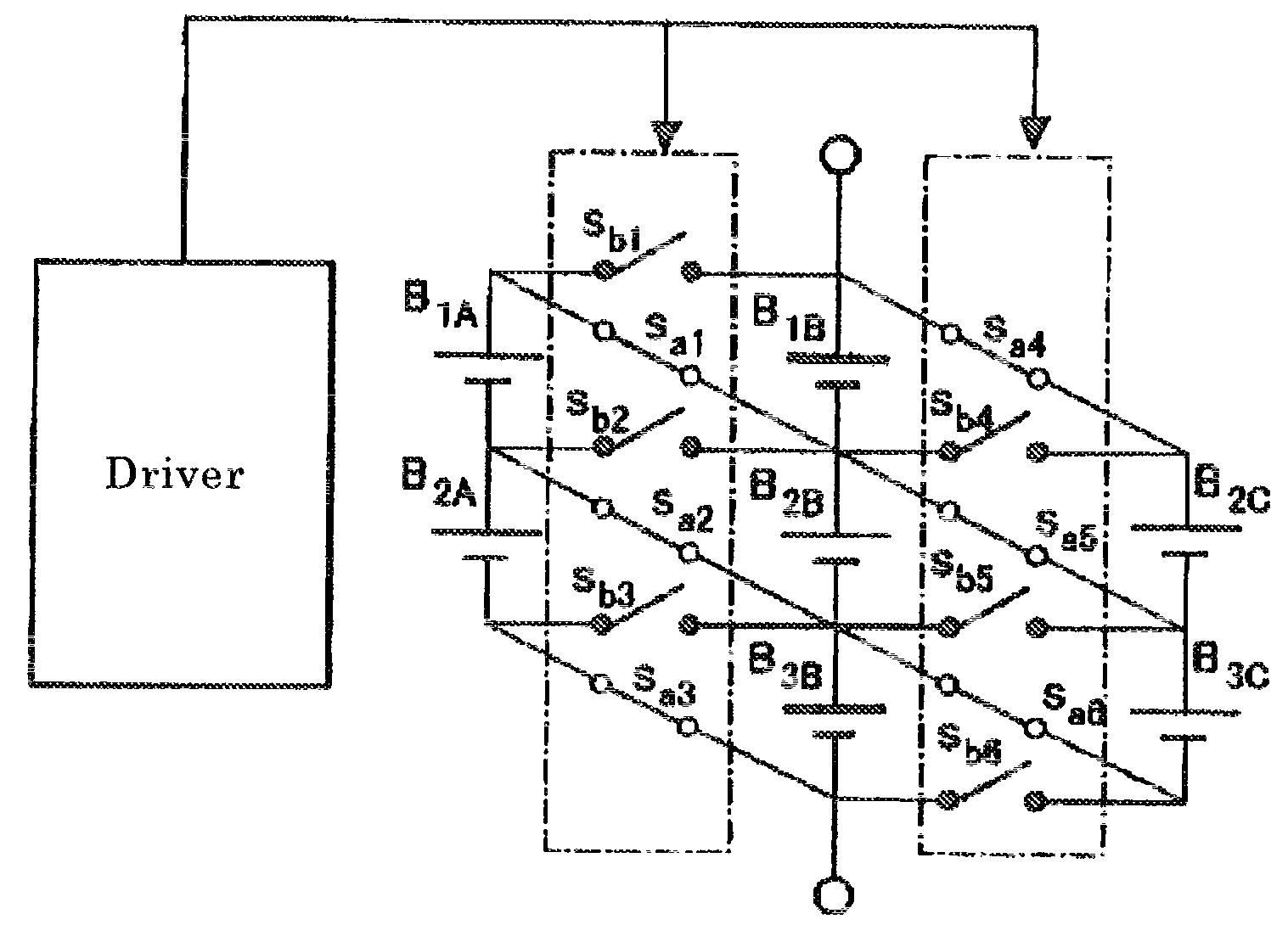
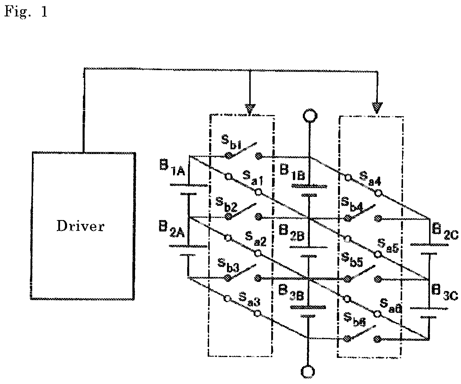
[0053]FIG. 8 is a circuit diagram illustrating a voltage equalization circuit 1 according to a first embodiment of the present invention, wherein a driver circuit portion connected to each switch is omitted.

[0054]The voltage equalization circuit 1 comprises: a first series circuit constructed by connecting three energy storage cells C1A, C2A, C3A in series; a second series circuit constructed by connecting two energy storage cells C1B, C2B in series; a third series circuit constructed by connecting two energy storage cells C1C, C2C in series; a first switch group consisting of six switches Sa1 to Sa6 as MOSFETs; and a second switch group consisting of six switches Sb1 to Sb6 as MOSFETs. The energy storage cells are selected to allow a ratio of a capacitance of each of the energy storage cells C2A, C1BC2B, C1C, C2C to a capacitance of each of the energy storage cells C1A, C3A to become 1:2.

[0055]When the energy ...

second embodiment

[Second Embodiment]

[0082]FIG. 13 is a circuit diagram of a voltage equalization circuit 1 according to a second embodiment of the present invention, wherein a driver circuit portion connected to each switch is omitted.

[0083]The circuit illustrated in FIG. 13 is provided as a configuration in which the number of energy storage cells serially connected in the first series circuit within the voltage equalization circuit 1 illustrated in FIG. 8 is increased to 6. The number of energy storage cells serially connected in the first series circuit may be set to any value. Even if a value of the number of energy storage cells serially connected in the first series circuit is changed, the voltage equalization circuit of the present invention can be operated on the same principle. The energy storage cells are selected such that a ratio of a capacitance of each of the energy storage cells C1A, C6A to a capacitance of each of the remaining energy storage cells is set to 2:1.

[0084]The number of e...

third embodiment

[Third Embodiment]

[0089]The energy storage module according to the previous patented invention is generalized as a circuit constructed by: alternately connecting, in parallel, (i) m series circuits each of which is constructed by connecting n energy storage cells or cell groups in series (wherein n is an integer of 2 or more) and (ii) m or m±1 multiple series circuits each of which is constructed by connecting (n−1) energy storage cells or cell groups in series (except for cases where the total number of parallel-connected series circuits is (4L−2), wherein L is a natural number). In view of this, the voltage equalization circuit of the present invention can also be generalized by constructing the switches comprised in the energy storage module according to the previous patented invention, as first and second switch groups, in accordance with teaching of the present invention. Specifically, the voltage equalization circuit illustrated in FIG. 8 can be said to be an example of a volt...


PUM


Abstract

It is an object to provide a circuit for equalizing voltages of energy storage cells, with less number of element and simpler circuit configuration than ever before.A plurality of field-effect transistors are arranged such that each of a plurality of parallel circuits formed, in one of connection states attained by switching of the switches, by connecting in parallel energy storage cells to perform mutual charging and discharging, includes a field-effect transistor adapted to avoid blocking a current having one of opposite polarities in the each of the plurality of parallel circuits, and a field-effect transistor adapted to avoid blocking a current having the other polarity in the each of the plurality of parallel circuits. This makes it possible to perform a voltage equalization operation using a small number of transistors.

Description

TECHNICAL FIELD[0001]The present invention relates to a cell voltage equalization circuit for equalizing cell voltages of a plurality of energy storage cells each composed of a capacitor, an electric double-layer capacitor, a lithium ion capacitor, a secondary battery or the like. In particular, the present invention relates to a series-parallel reconfigurable cell voltage equalization circuit adapted to be operated according to switching of a field-effect transistor (FET) switch, such as a metal-oxide semiconductor field-effect transistor (MOSFET) switch.BACKGROUND ART[0002]Generally, as a prerequisite to operating a certain device by an electric power, it is necessary to perform power feeding within a given operating voltage range which is determined by characteristics of the device. Further, an energy storage-type power supply system usable, for example, as an uninterruptible power supply (UPS) for emergency purposes, is required to have a sufficiently high capacitance so as to e...

Claims


Application Information

Patent Timeline
Patent Type & Authority Patents(United States)
IPC IPC(8): H02J1/00H02J7/02
CPCH02J7/0014H02J7/0024Y10T307/685H02J7/0018H03K17/687H03K2017/6878
Inventor UNO, MASATOSHIKUKITA, AKIOITO, KAZUSHIGESEKIDO, TSUTOMUNAGATA, KAORUSHOJI, KAZUHIRO
Owner JAPAN AEROSPACE EXPLORATION AGENCY
Why Eureka
Try Eureka