Piezoelectric element, liquid ejecting head, and liquid ejecting apparatus

a liquid ejecting head and liquid ejecting technology, applied in the direction of device material selection, inking apparatus, printing, etc., can solve the problems of ferrite-based piezoelectric material, cracks are more likely to occur, so as to achieve low environmental burden

Inactive Publication Date: 2014-05-13
SEIKO EPSON CORP
View PDF8 Cites 1 Cited by
  • Summary
  • Abstract
  • Description
  • Claims
  • Application Information

AI Technical Summary

Benefits of technology

[0009]An advantage of some aspects of the invention is that it provides a liquid ejecting head in which an environmental burden is low and an occurrence of cracks is suppressed, a liquid ejecting apparatus, and a piezoelectric element that provides these.

Problems solved by technology

However, since lead zirconate titanate contains lead, from the viewpoint of environmental problems, a piezoelectric material that does not contain lead is required.
The bismuth ferrite-based piezoelectric material has a problem in that cracks are more likely to occur, compared to the piezoelectric layer made of the piezoelectric material containing lead.
In particular, there are problems in that cracks are more likely to occur when a thick piezoelectric layer (for example, a piezoelectric layer of equal to or greater than 750 nm) is formed and it is difficult to form a thick piezoelectric layer made of a bismuth ferrite-based material.
In addition, of course, such problems occur not only in the ink jet type recording head, but also in other liquid ejecting heads that discharge liquid droplets other than ink, and also occur in piezoelectric elements used for devices other than the liquid ejecting head.

Method used


Image

  • Piezoelectric element, liquid ejecting head, and liquid ejecting apparatus
  • Piezoelectric element, liquid ejecting head, and liquid ejecting apparatus
  • Piezoelectric element, liquid ejecting head, and liquid ejecting apparatus

Examples


first embodiment

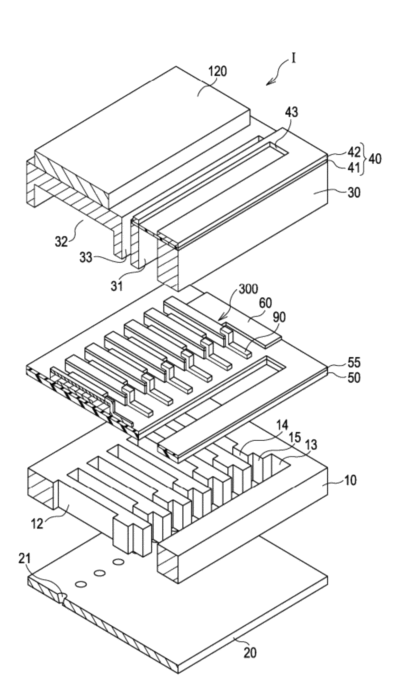
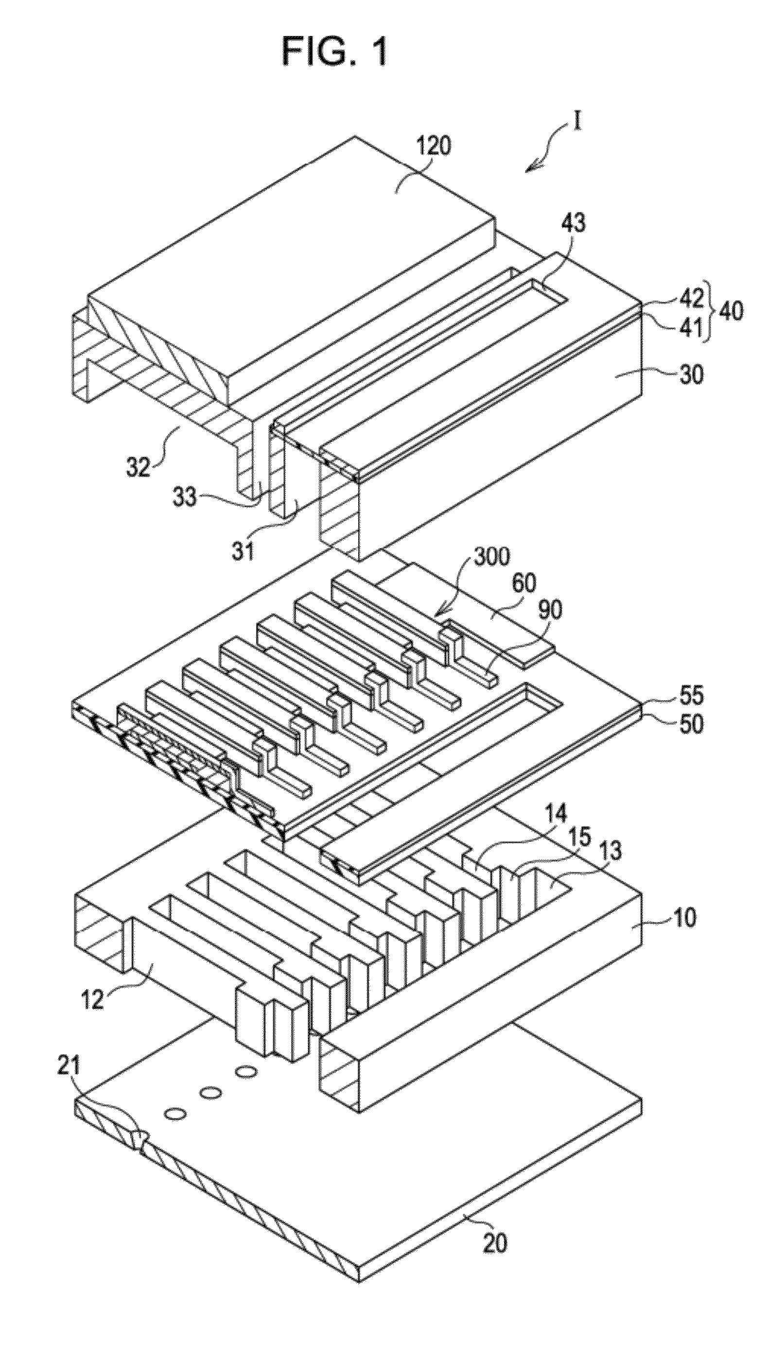
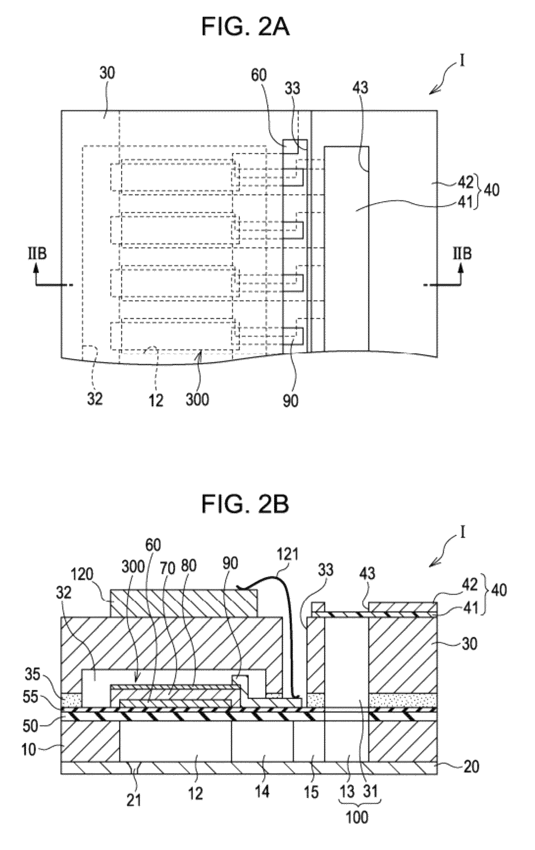
[0035]FIG. 1 is an exploded perspective view of an ink jet type recording head which is an example of a liquid ejecting head according to a first embodiment of the invention. FIGS. 2A and 2B are a plan view of FIG. 1 and a cross-sectional view taken along the line IIB-IIB.

[0036]In a flow path formation substrate 10, a plurality of pressure generation chambers 12 are arranged in parallel in the width direction. In addition, a communication portion 13 is formed in an outer region in the longitudinal direction of the pressure generation chamber 12 of the flow path formation substrate 10, and the communication portion 13 communicates with each of the pressure generation chambers 12 via an ink supply path 14 and a communication path 15 provided for each of the pressure generation chambers 12. The communication portion 13 communicates with a manifold portion 31 of a protective substrate described later and configures a part of a manifold which is a common ink chamber of the pressure gener...

example 1

[0078]First, a silicon dioxide (SiO2) film having a thickness of 1200 nm was formed on the surface of a (100)-oriented single crystal silicon (Si) substrate by thermal oxidation. Next, a titanium film having a thickness of 40 nm was produced on the SiO2 film by an RF magnetron sputtering method, and thermal oxidation was performed thereon, thereby forming a titanium oxide film. Next, a (111)-oriented platinum film (first electrode 60) having a thickness of 100 nm was formed on the titanium oxide film by the RF magnetron sputtering method.

[0079]Thereafter, the piezoelectric layer 70 was formed on the first electrode 60 by a spin coating method. The method is as follows. First, an n-octane solution of bismuth 2-ethylhexanoate, iron 2-ethylhexanoate, manganese 2-ethylhexanoate, barium 2-ethylhexanoate, titanium 2-ethylhexanoate, and zinc 2-ethylhexanoate was mixed at a predetermined ratio, thereby preparing a precursor solution.

[0080]The precursor solution was dropped on the substrate ...

example 2

[0082]The same operations as those of the Example 1 were performed except that the piezoelectric layer 70 containing a composite oxide made of a mixed crystal expressed by 0.85{Bi(Fe0.94,Mn0.06)O3}-0.10{BaTiO3}-0.05{Bi(Zn0.5,Ti0.5)O3} was used by changing blending amounts of various metal complexes in the precursor solution.


PUM

PropertyMeasurementUnit
thickaaaaaaaaaa
thicknessaaaaaaaaaa
thicknessaaaaaaaaaa

Abstract

A piezoelectric element comprises a piezoelectric layer and an electrode provided with the piezoelectric layer. The piezoelectric layer is made of a composite oxide containing bismuth ferrite, barium titanate, and bismuth zinc titanate.

Description

CROSS-REFERENCE TO RELATED APPLICATIONS[0001]The entire disclosure of Japanese Patent Application No. 2011-039041, filed Feb. 24, 2011 is expressly incorporated by reference.BACKGROUND[0002]1. Technical Field[0003]The present invention relates to a liquid ejecting head including a piezoelectric element which causes a pressure change in a pressure generation chamber communicating with a nozzle opening and has a piezoelectric layer and an electrode that applies a voltage to the piezoelectric layer, a liquid ejecting apparatus, and the piezoelectric element.[0004]2. Related Art[0005]As a piezoelectric element used in a liquid ejecting head, there is a piezoelectric element configured by interposing a piezoelectric layer made of a piezoelectric material that presents a electromechanical conversion function, for example, a crystallized dielectric material between two electrodes. Such a piezoelectric element is mounted in the liquid ejecting head as, for example, an actuator device in a f...

Claims


Application Information

Patent Timeline
Patent Type & Authority Patents(United States)
IPC IPC(8): B41J2/045H01L41/18H01L41/22H01L41/318H01L41/39
CPCB41J2202/03H01L41/0805H01L41/187H01L41/318B41J2/14233H10N30/1051H10N30/853H10N30/078
Inventor SAKAI, TOMOHIRO
Owner SEIKO EPSON CORP
Why Eureka
Try Eureka