Methods for performing model-based lithography guided layout design

Active Publication Date: 2014-05-20
ASML NETHERLANDS BV
View PDF49 Cites 10 Cited by
  • Summary
  • Abstract
  • Description
  • Claims
  • Application Information

AI Technical Summary

Benefits of technology

[0023]The present invention provides significant advantages over prior art methods. Most importantly, the present invention provides a systematic, fast and cost effective model-based method for optimizing the placement of the main features (i.e.,

Problems solved by technology

These rules are set by processing and design limitations.
This trend towards “sub-wavelength lithography” has resulted in increasing difficulty in maintaining adequate process margins in the lithography process.
There is limited practical flexibility in choosing the exposure wavelength, while the numerical aperture of exposure tools is approaching physical limits.
Consequently, the continuous reduction in device feature sizes requires more and more aggressive reduction of the k1 factor in lithographic processes, i.e. imaging at or below the classical resolution limits of an optical imaging system.
The cost of manufacturing advan

Method used


Image

  • Methods for performing model-based lithography guided layout design
  • Methods for performing model-based lithography guided layout design
  • Methods for performing model-based lithography guided layout design

Examples


Example

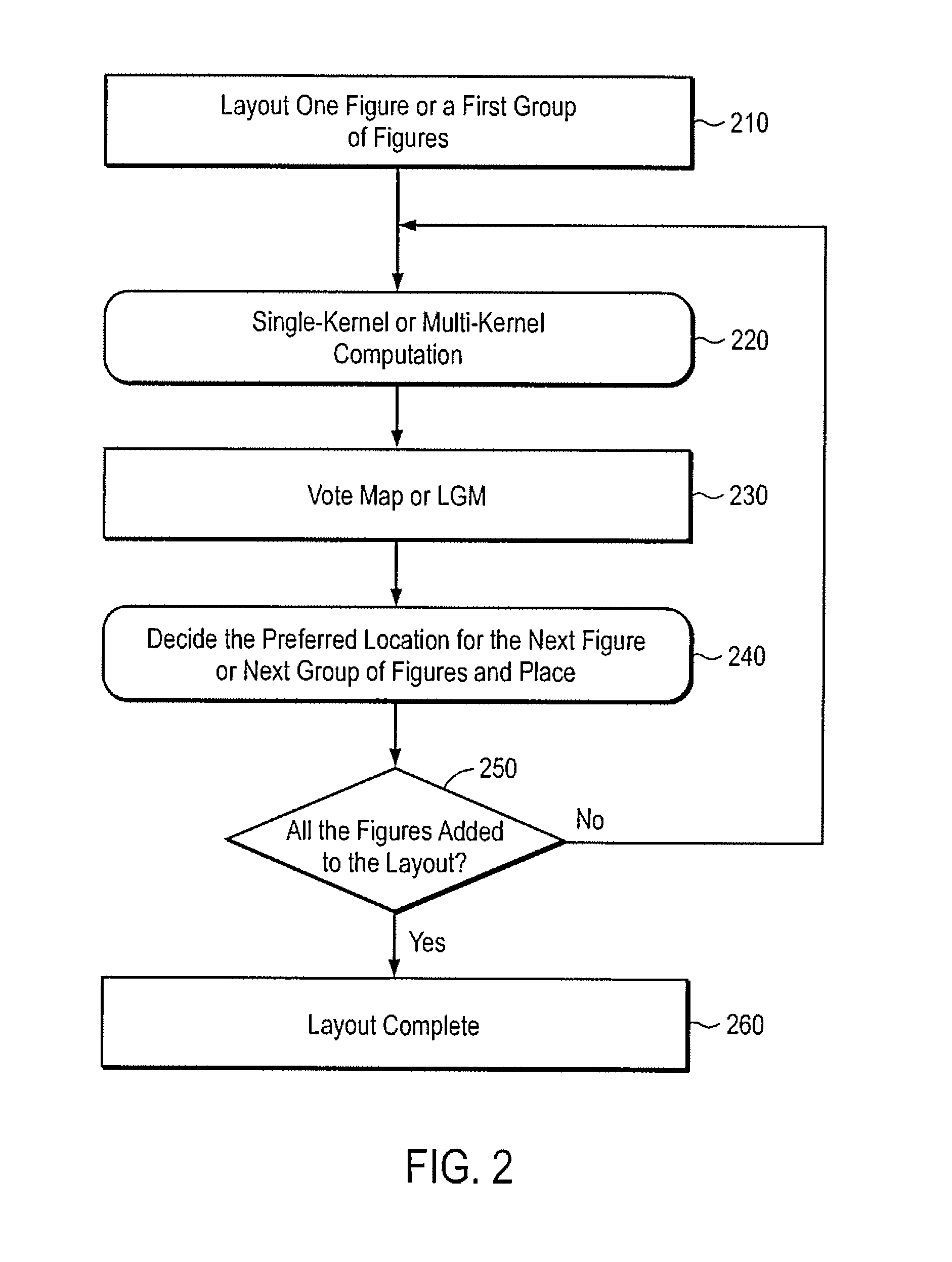
[0043]FIG. 2 is an exemplary flowchart illustrating an exemplary process of the LGL process of the present invention. In the first step of the process (Step 210), utilizing the target design, one or more of the features included in the target design are placed in a mask pattern in accordance with their corresponding positions in the target pattern. It is noted that the number of features from the target pattern to be added to the mask pattern each iteration can be determined, for example, by the operator, or may be defined as some fixed number, or may be governed by the process being utilized and the number of features deemed critical in the target design. In another variation, it is possible to add only a single feature per iteration.

[0044]At step 220, a simulation of the illumination of the current mask pattern for a given lithography process (i.e., the process to be utilized to illuminate the target pattern) is performed so as to produce an aerial image (or equivalent thereof) wh...


PUM


Abstract

Methods are disclosed to create efficient model-based Sub-Resolution Assist Features (MB-SRAF). An SRAF guidance map is created, where each design target edge location votes for a given field point on whether a single-pixel SRAF placed on this field point would improve or degrade the aerial image over the process window. In one embodiment, the SRAF guidance map is used to determine SRAF placement rules and/or to fine-tune already-placed SRAFs. The SRAF guidance map can be used directly to place SRAFs in a mask layout. Mask layout data including SRAFs may be generated, wherein the SRAFs are placed according to the SRAF guidance map. The SRAF guidance map can comprise an image in which each pixel value indicates whether the pixel would contribute positively to edge behavior of features in the mask layout if the pixel is included as part of a sub-resolution assist feature.

Description

CROSS REFERENCE TO RELATED APPLICATIONS[0001]This application is the U.S. National Stage Application (filed under 35 U.S.C. 371) of prior International Application No. PCT / US2008 / 065656, filed Jun. 3, 2008, and published on Dec. 11, 2008 as WO 2008 / 151185, which claims the benefit of / priority to U.S. application Ser. No. 11 / 757,805, filed Jun. 4, 2007, entitled “System and Method for Model-Based Sub-Resolution Assist Feature Generation”, issued on Feb. 1, 2011 as U.S. Pat. No. 7,882,480, and also claims the benefit of / priority to U.S. provisional application No. 60 / 935,713, filed Aug. 28, 2007.FIELD OF THE INVENTION[0002]This invention relates generally to resolution enhancement techniques for photolithography and relates more particularly to a system and method for model-based lithography guided layout.BACKGROUND[0003]Lithographic apparatus can be used, for example, in the manufacture of integrated circuits (ICs). In such a case, the mask may contain a circuit pattern corresponding...

Claims


Application Information

Patent Timeline
IPC IPC(8): G06F17/50G03F1/00G03F1/36
CPCG03F1/144G03F1/36G06F17/5009G03F7/70433G03F7/70441G03F7/70666G03F1/68G03F7/20G06F30/20
Inventor YE, JUNCAO, YUFENG, HANYING
Owner ASML NETHERLANDS BV
Why Eureka
Try Eureka