Method for writing high power resistant Bragg gratings using short wavelength ultrafast pulses

a technology of ultrafast pulses and bragg gratings, which is applied in the field of writing bragg gratings, can solve the problems of increasing intra-cavity losses, affecting the performance of the bragg grating, and the strength of the high-order grating at the wavelength of interest may not always be sufficient, so as to reduce the effects of photoinduced losses, and reduce the loss of grating strength

Active Publication Date: 2014-05-27
UNIV LAVAL
View PDF5 Cites 7 Cited by
  • Summary
  • Abstract
  • Description
  • Claims
  • Application Information

AI Technical Summary

Benefits of technology

[0011]The method further includes heating the region of the waveguide containing the Bragg grating to a temperature above a temperature threshold and for a predetermined heating period. The temperature threshold and heating period are sufficient to substantially reduce photoinduced losses in the waveguide.
[0013]Advantageously, the heating step above allows the elimination of photoinduced losses effects which would otherwise be present and therefore alter the waveguiding properties of the waveguide.
[0014]The glass waveguide may be made of a photosensitized or a non-photosensitized material. It has been found that even FBGs inscribed in standard optical fibers experience some losses that can be problematic when used at very high optical power, and that embodiments of the present invention can mitigate these losses.
[0019]d) propagating a light beam in the waveguide, the light beam having an intensity sufficient to heat the region of the optical fiber containing the Bragg grating to a temperature above a temperature threshold for a predetermined heating period. The temperature threshold and heating period are sufficient to substantially reduce photoinduced losses in the optical fiber.

Problems solved by technology

Those splices may lead to additional intra-cavity losses and are not suited for some active fiber geometries, particularly when high power operation is required.
The amount of loss induced during the FBG writing process in any type of fiber will define its power handling, such loss can then be detrimental to some applications.
However, for high power applications, the strength of the high order grating at the wavelength of interest may not always be sufficient.

Method used


Image

  • Method for writing high power resistant Bragg gratings using short wavelength ultrafast pulses
  • Method for writing high power resistant Bragg gratings using short wavelength ultrafast pulses
  • Method for writing high power resistant Bragg gratings using short wavelength ultrafast pulses

Examples


examples

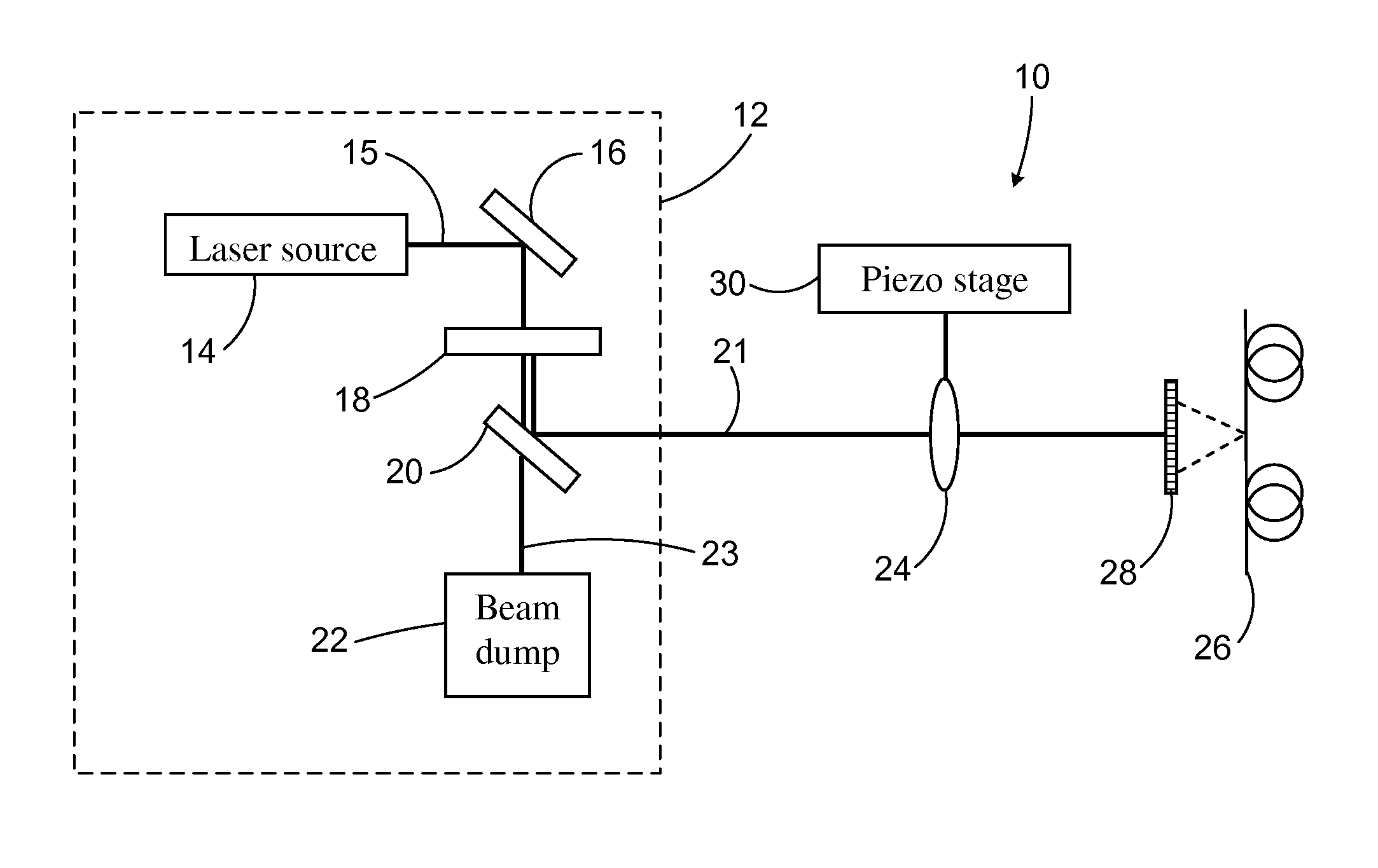
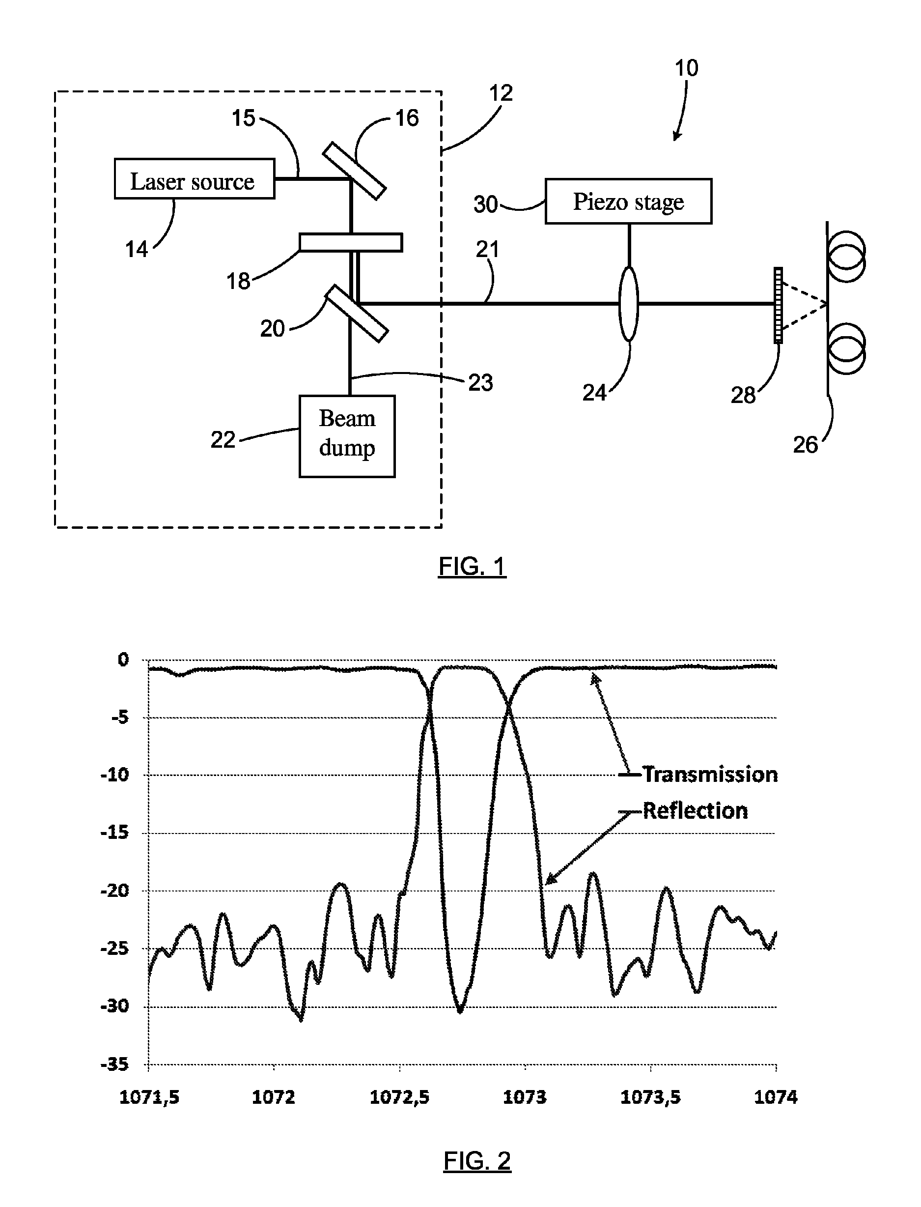
[0064]In one example of an embodiment of the invention, a Bragg grating was written in an optical fiber using a system similar to the one illustrated at FIG. 1. The waveguide used in this experiment was a double cladding ytterbium doped silica fiber. The pump core of the double cladding fiber had a diameter of 128 μm with an octogonal shaped geometry while the signal core had a 6 μm diameter and was co-doped solely with 2 mol % of Al2O3, hence no photosensitive element such as germanium was added to the fiber glass composition.

[0065]A Ti-sapphire regenerative amplifier system (Coherent Legend-HE, trademark) that produces fs-laser pulses of 3.5 mJ per pulse at 1 kHz repetition rate with central wavelength at λ=806 nm was used as pump source. The duration of the Fourier-transform limited pulses was measured to be about 35 fs. A BBO crystal (Eksma Optics, BBO-1502, trademark) was used to produce a maximum of 1.0 mJ of second harmonic at 403 nm. A dichroic mirror was used to separate th...


PUM


Abstract

A method for writing a Bragg grating in a glass optical waveguide is provided. Ultrafast optical pulses are generated, preferably in the femtosecond range and having a writing wavelength in the range of 300 nm to 700 nm and an intensity sufficient to induce a change of refractive index in the waveguide through densification. The optical pulses are diffracted using a phase mask, to generate an interference pattern having a pitch providing a fundamental Bragg resonance corresponding to the target wavelength to be reflected by the grating. The interference pattern is impinged on a region of the waveguide, which is heated to a temperature above a threshold and for a predetermined heating period. Advantageously, the heating step allows the reduction of photoinduced losses which would otherwise be present in the waveguiding properties of the waveguide. Optionally, gratings may be written through the polymer jacket of an optical fiber.

Description

FIELD OF THE INVENTION[0001]The present invention relates to the field of Bragg gratings manufacturing and more particularly concerns a method for writing Bragg gratings with low-losses in waveguides, particularly suitable for high optical power applications, using short wavelength ultrafast pulses.BACKGROUND[0002]High optical power applications, such as high power fiber lasers, require strong Bragg gratings which are resistant to the high intensity of light circulating in the optical fiber.[0003]Gratings obtained using the defect-resonant UV-induced physical process that is commonly used for the writing of fiber Bragg gratings (FBGs) in silica fibers are restricted to photosensitive fibers and cannot generally be inscribed in the rare-earth doped fibers used as laser gain media. This in turn implies that fiber laser cavities will require fusion splices between the active fiber and the photosensitive ones. Those splices may lead to additional intra-cavity losses and are not suited f...

Claims


Application Information

Patent Timeline
Patent Type & Authority Patents(United States)
IPC IPC(8): G02B6/34
CPCB29D11/00663G02B6/02204G02B6/02138
Inventor VALLEE, REALBERNIER, MARTIN
Owner UNIV LAVAL
Why Eureka
Try Eureka