Device for shaping object with a profile of at least a partial sphere

a technology a device, which is applied in the field of shaping a plurality of objects with a profile of at least a partial sphere, can solve the problems of increased manufacturing costs, increased manufacturing costs, and increased manufacturing costs, and achieves less insertion profiles, small size, and simple structure

Inactive Publication Date: 2014-07-08
XIE PING +1
View PDF53 Cites 22 Cited by
  • Summary
  • Abstract
  • Description
  • Claims
  • Application Information

AI Technical Summary

Benefits of technology

[0016]An advantage of the present invention is that a reamer is designed under a new cutting principle and has a simple structure and smaller size, which has less insertion profile, is of relatively easy operation and more cost effective to manufacture.

Problems solved by technology

When the reamer as described above is used to prepare a spherical cavity for hip joint prosthesis, several problems are raised.
Firstly, the key issues related to the performance of the reamer are that the sharpness and shape of the cutting edges are good enough to generate a qualified surface and accuracy regardless the linear cutting speed acted on.
Thirdly, the preparation procedure for the acetabulum needs the enlarging of the native socket to a precise hemisphere.
This procedure may be repeated several times until the cavity matches the dimension of the prosthetic, causing unnecessary prolonged surgical time.
Such minor changes have brought some improvements, but also new problems as a trade off, such as more complicated structures, higher manufacturing costs and increased inconvenience of use.
The drawbacks and challenges on this conventional design have been well exposed through practices over the years.
This requirement takes into account fact that new bone growths cannot bridge large gap distances.
If the sharpness of the cutting edge is not good enough to overcome hard bone faced at lower linear cutting speed, the cavity reamed would hardly meet the minimum requirement for roundness needed for proper press fitting of the metal cup and as a result, an optimal cup fixation by new growth bone cannot be achieved.
Obviously, such larger gaps existed might reduce both the initial and long term stability of implant.
But the elastic behavior of bone from an ill patient is typically either too rigid or too yielding to control the outcomes of installation, therefore making the tolerance of size difference between two objects more difficult to be estimated during installation and critical for maintaining stability thereafter.
But the new bone growth can only cross certain gap distances to bridge surfaces between bone surface and cup attachments.
Although the roundness and radius may be acceptable in the macro sense, the distance between the two surfaces in groove area may be still too large to encourage new bone growing into the cup attachment.
In other words, the failures or side effects resulting from such surgery might most likely attribute to the limitations on tool's functions or flaws of the tool rather than a surgeon's experience or skill.
In practice, the hemispherical dome reamers fail to run on fast cutting rates due to concern about the varying linear speeds along the different latitudes of the sphere, the jagged resistance met, due to occasional deep cutting, and friction heat generated by some blunt or blocked cutting edges lost function.
The stability and self centralization ability refers to the wobbling or vibration of the reamer during the reaming process, which could lead to shift the cutter and miscut.
Another performance concern is the size of the reamer.
The larger size of a full hemispherical cutting element is unavoidable in the traditional reamer since the size of hemispherical dome cutter needs to match one of each cavity sought to be reamed.
Currently the needs for changing cutting heads during the cavity enlargement procedure is very inconvenient and impractical for MIS, since it is very time consuming, causes more damage, and inefficient on tuning the size reamed.
Currently, even though the structure of hemispherical domed reamer is quite simple, the manufacturing and maintenance of this structure is very complicated and costly.
This is due to the complexity and costs of the materials used, the special processing applied during its manufacturing, and the maintenance required for preserving the sharpness of the cutting elements.

Method used


Image

  • Device for shaping object with a profile of at least a partial sphere
  • Device for shaping object with a profile of at least a partial sphere
  • Device for shaping object with a profile of at least a partial sphere

Examples


Embodiment Construction

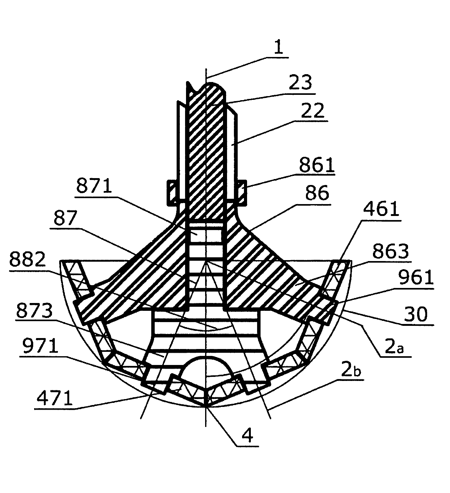
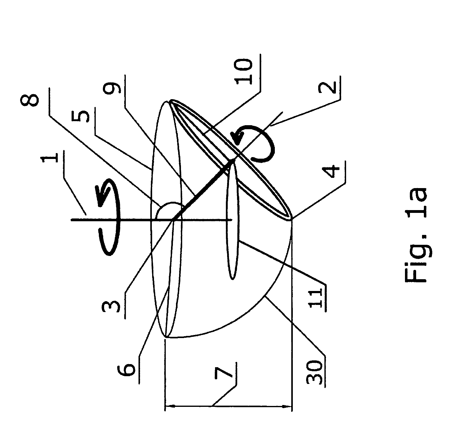
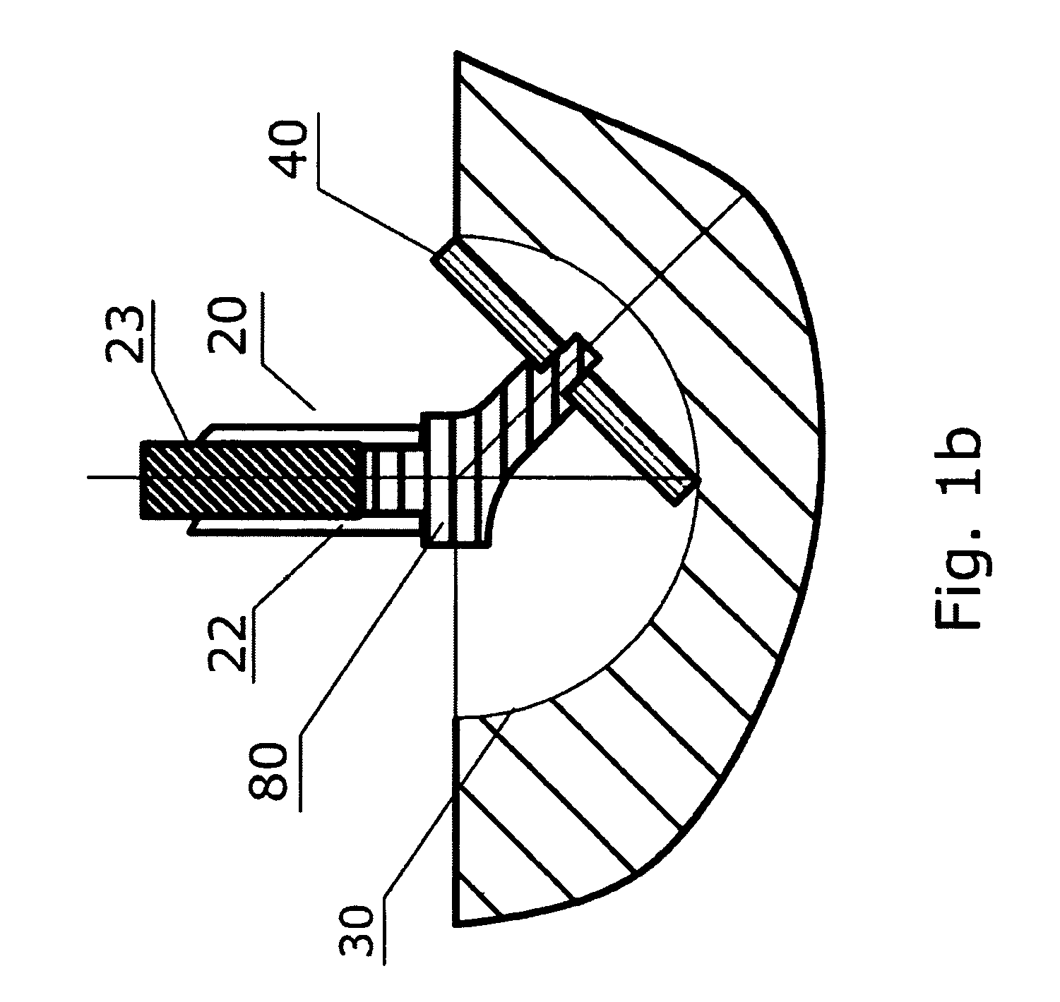
[0028]Referring now to the drawings, and more particularly to FIG. 1a, there is a sketch drawing of the geometrical principle of the reamer and defined parameters and definitions used on describing the invention are:

DEFINITION

[0029]Primary axis 1: the rotary axis of the reamer and also corresponding to the polar axis of the sphere sought to be cut.

[0030]Secondary axis 2: the axis passes through the circular center of the cutting edge and corresponds to the spinning axis of the cutting element.

[0031]Virtual center 3 of the reamer assembly or of the featured frame: the intersection point of the primary axis with the secondary axis of each cutting element and also conforms to the center point of the sphere sought to be reamed.

[0032]Apex point of reamer assembly 4: the lowest point of the reamer assembly, and equivalent to the polar point of the sphere sought to be reamed.

[0033]Equatorial circle 5: the horizontal circle / plane of the reamer assembly with a center at the virtual center an...


PUM


Abstract

A device for shaping an object with a profile of at least partial sphere defined by a radius, Rsph and a maximum breadth, Dmax of the sphere comprises at least one featured frame. A cutting element has been substantially positioned on a position located within a circular orbit by the featured frame and shaped with at least a portion of circular cutting edge with a uniform radius, rCE, which is able to free spinning-able on its spinning axis while, simultaneously the featured frame revolts on a circular orbit around the polar axis of the spherical object. The circular orbit of each cutting element is defined as a motion track of a circular center of the cutting edge around the polar axis and characterized by a radius, rorb, and a tilted angle α, thereof.

Description

FIELD OF THE INVENTION[0001]The invention is especially, but not exclusively, applicable to the field of shaping a plurality of object having a profile of at least partial sphere. The present invention could relate orthopedic reamers and other industrial applicability, or like.DESCRIPTION OF THE PRIOR ART[0002]The reamers for reshaping bone sockets are used widely in current procedures, such as total hip arthroplasty (THA). The plurality of reamers previously invented in the past mostly has derived from idea of the “convex-concave match” design and could be described as that a fully hemispherical thin wall with a specific radius, on which a few cutting edges are projected and well distributed on the convex surface of the wall, forms a hemispherical “cheese grater”. Each cutting edge forms a narrow passage conducting from the exterior hemispherical surface into the internal chamber of the cutting head. In particular, the cutting edges may be distributed along a spiral line toward the...

Claims


Application Information

Patent Timeline
Patent Type & Authority Patents(United States)
IPC IPC(8): A61B17/00A61B17/16
CPCA61B17/1666
Inventor XIE, PINGLI, XUE
Owner XIE PING
Why Eureka
Try Eureka