
Catalyst for generating hydrogen and method for generating hydrogen

a hydrogen and catalyst technology, applied in the direction of electrochemical generators, metal/metal-oxide/metal-hydroxide catalysts, physical/chemical process catalysts, etc., can solve the problems of large-scale equipment, large energy requirements for hydrogen generation, and large amount of hydrogen generated, etc., to achieve high selectivity and efficient generation

Inactive Publication Date: 2014-07-22
NAT INST OF ADVANCED IND SCI & TECH
View PDF12 Cites 2 Cited by
  • Summary
  • Abstract
  • Description
  • Claims
  • Application Information

AI Technical Summary

Benefits of technology

The invention provides a method for generating hydrogen gas efficiently without heating to a high temperature. The method uses a low-cost catalyst that does not require any precious metals. The resulting hydrogen gas is highly suitable for use as a fuel for fuel cells in automobiles and portable fuel cells.

Problems solved by technology

However, these methods have drawbacks in which much energy is required to generate hydrogen, the amount of hydrogen generated is small relative to the amount of starting materials used, large-scale equipment is required, etc.
For this reason, although these methods are applicable to hydrogen generation on an industrial scale or on a laboratory scale, they are not suitable for use in supplying hydrogen to fuel cells for automobiles, portable fuel cells for, for example, cellular phones and personal computers, and the like, which require a continuous supply of necessary amounts of hydrogen fuel, and for which there is a demand for miniaturization.
These compounds need to be handled carefully because they rapidly release a large amount of hydrogen upon contact with water, producing an explosive phenomenon.
For this reason, these compounds are also not suitable for use as hydrogen supply sources for the fuel cells mentioned above.
However, these methods have problems related to the recovery and regeneration of the resulting borate compounds.
However, an investigation of the ability of these metal catalysts to catalyze the generation of hydrogen via decomposition reactions of hydrazine revealed that a sufficient amount of hydrogen is not produced using these catalysts (see Non-Patent Literature 5 below).
However, Patent Literature 5 does not disclose the details of a method for generating hydrogen by the decomposition of hydrazine.
However, according to these methods, hydrogen is not produced from hydrazine at a high yield, resulting in an insufficient amount of hydrogen.

Method used


Image

  • Catalyst for generating hydrogen and method for generating hydrogen
  • Catalyst for generating hydrogen and method for generating hydrogen
  • Catalyst for generating hydrogen and method for generating hydrogen

Examples


example 1

[0072]NiCl2.6H2O (0.024 g), FeSO4.7H2O (0.028 g), hexadecyltrimethylammonium bromide (CTAB, 95%) (0.100 g), and water (2.5 mL) were placed in a 30-mL two-necked flask, and the mixture was ultrasonically stirred for 5 minutes, followed by heating at 50° C. for 5 minutes. An NaBH4 (0.010 g) aqueous solution (1.5 mL) was subsequently added, and the reactor was vigorously shaken for 5 minutes, thereby forming an NiFe nanoparticle catalyst.

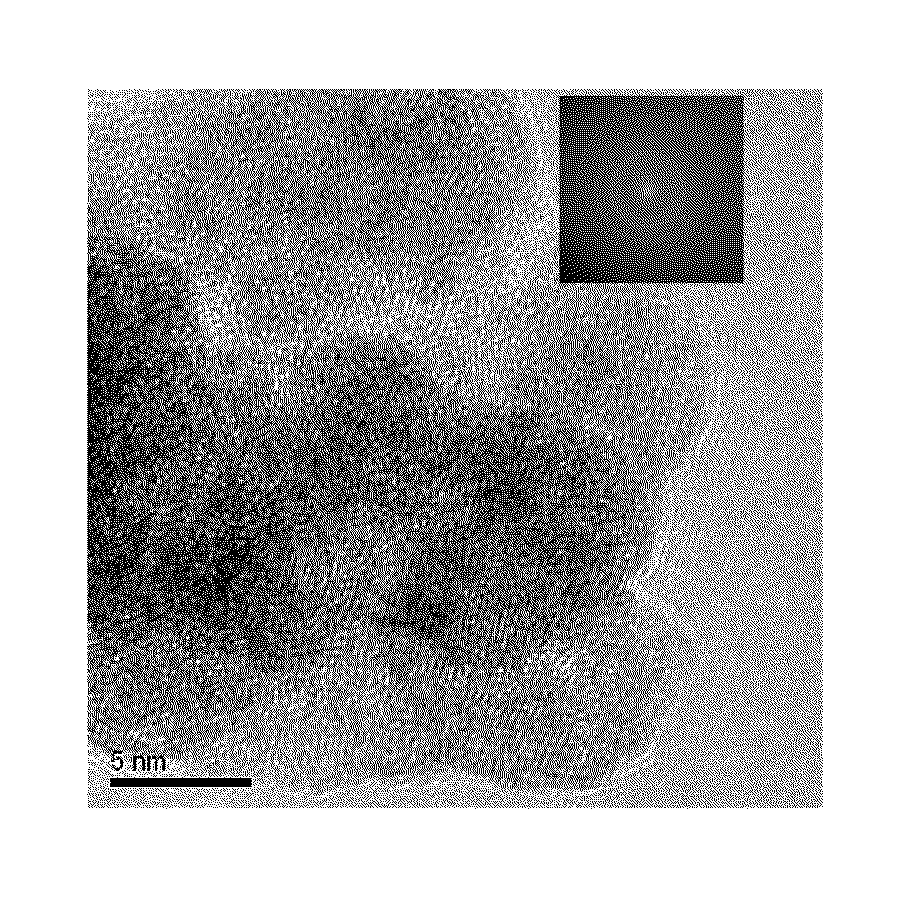
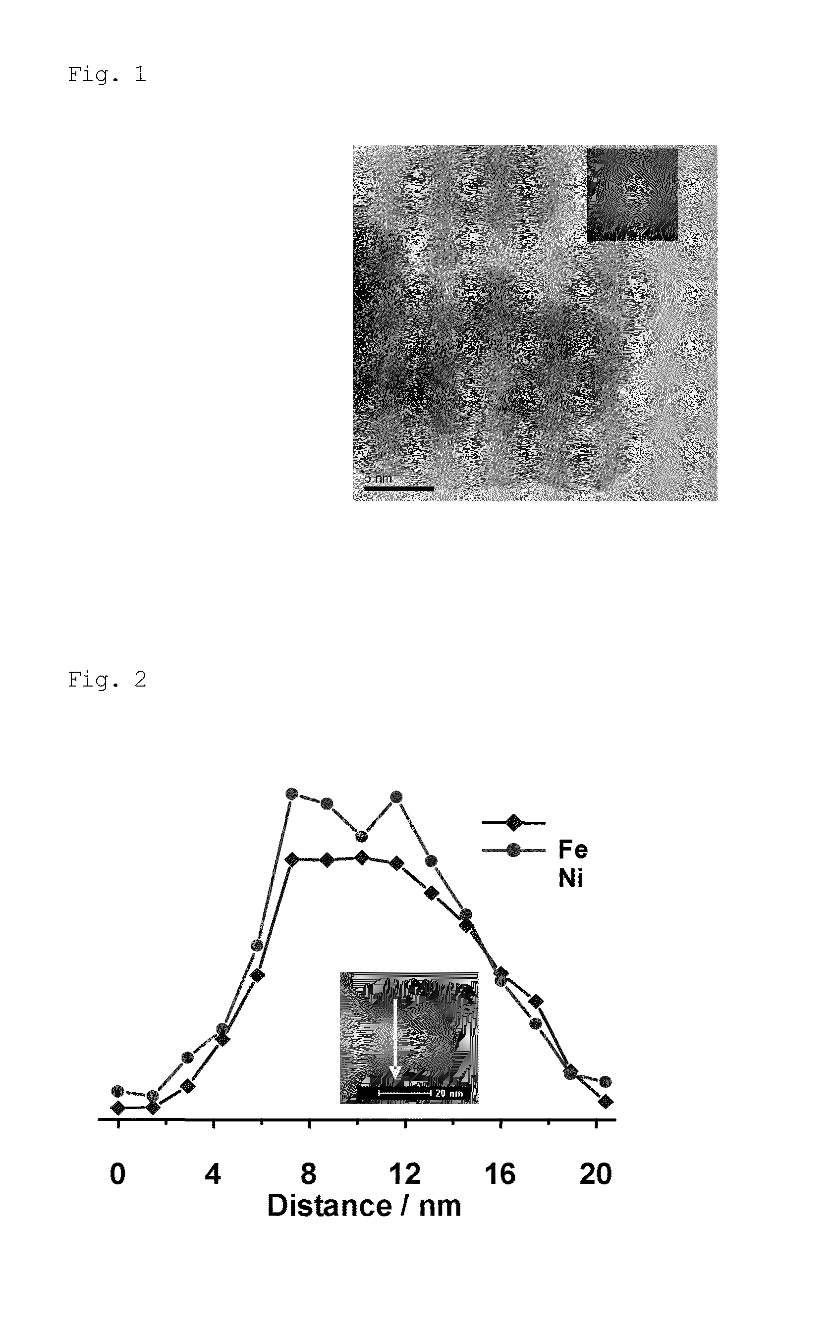
[0073]A transmission electron microscope (TEM) image of the NiFe nanoparticle catalyst obtained is shown in FIG. 1. As is clear from FIG. 1, the catalyst was composed of ultrafine particles having a particle size of about 10 nm.

[0074]FIG. 2 shows a high-angle annular dark-field (scanning transmission electron microscope) (HAADF-STEM) image of the NiFe nanoparticle catalyst; it shows the EDS line scan spectral intensities of Fe and Ni measured along the line shown in the figure. It can be clearly seen from the EDS line scan spectra shown in FIG. 2 that ...

example 2

[0084]NiCl2.6H2O (0.024 g), FeSO4.7H2O (0.028 g), hexadecyltrimethylammonium bromide (CTAB, 95%) (0.100 g), and water (2.5 mL) were placed in a 30-mL two-necked flask, and the mixture was ultrasonically stirred for 5 minutes, followed by heating at 50° C. for 5 minutes. An NaBH4 (0.010 g) aqueous solution (1.5 mL) was subsequently added, and the reactor was vigorously shaken for 5 minutes, thereby forming an NiFe nanoparticle catalyst.

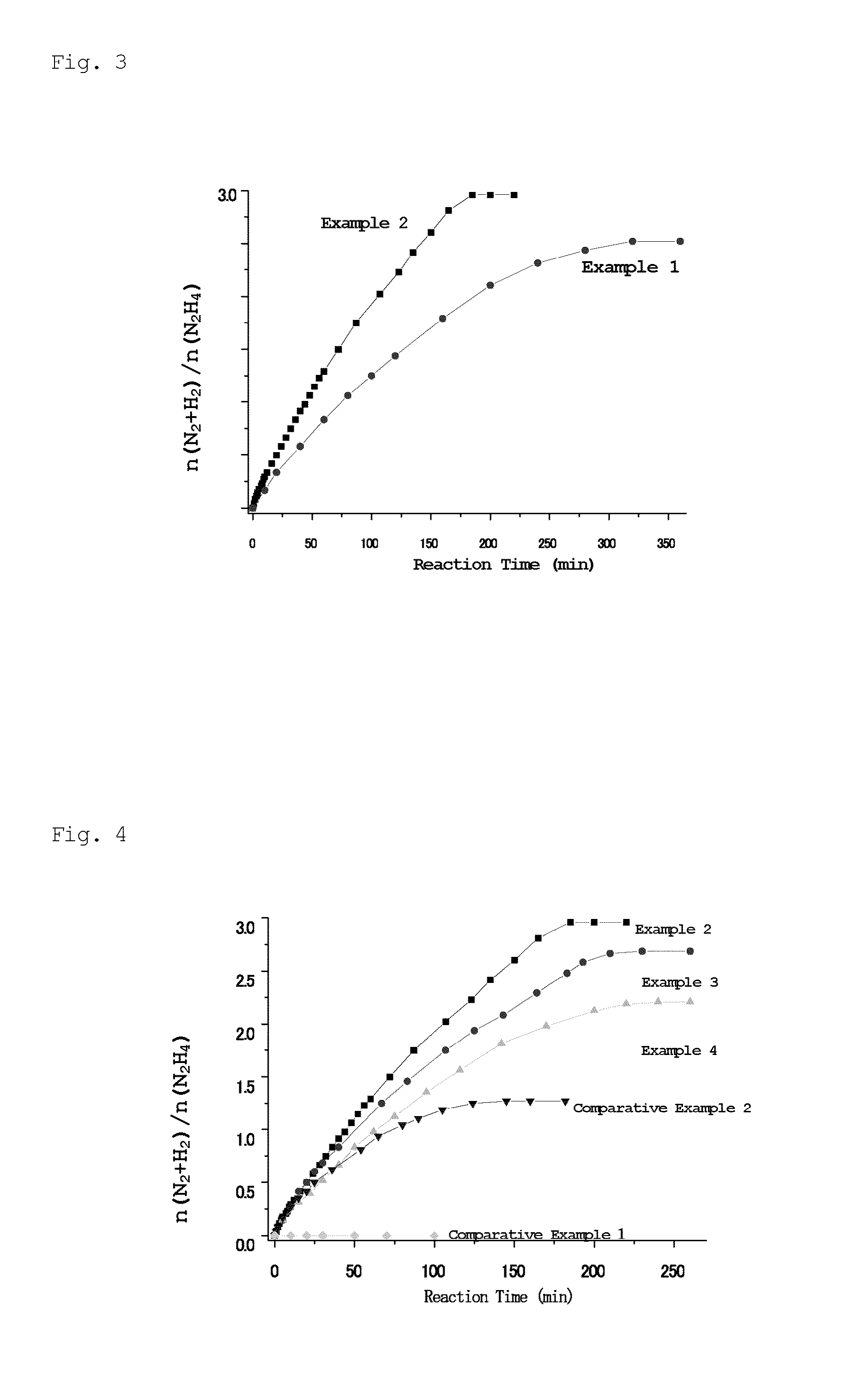
[0085]NaOH (0.080 g) was then added to the solution obtained above and the reactor was shaken to dissolve the NaOH. Hydrazine monohydrate (H2NNH2.H2O, 99%) (0.1 mL, 1.97 mmol) was added to the two-necked flask via a syringe, and stirring was continued at 70° C. Released gases were passed through a trap containing 1.0 M hydrochloric acid, where ammonia was absorbed; subsequently, only hydrogen and nitrogen were introduced into a gas burette, and the amount of the released gases was measured. After 10, 20, 32, 60, 107, 150, 185, and 220 minutes from the ...

example 3

[0089]NiCl2.6H2O (0.036 g), FeSO4.7H2O (0.014 g), hexadecyltrimethylammonium bromide (CTAB, 95%) (0.100 g), and water (2.5 mL) were placed in a 30-mL two-necked flask, and the mixture was ultrasonically stirred for 5 minutes, followed by heating at 50° C. for 5 minutes. An NaBH4 (0.010 g) aqueous solution (1.5 mL) was subsequently added, and the reactor was vigorously shaken for 5 minutes, thereby forming an Ni3Fe nanoparticle catalyst.

[0090]NaOH (0.080 g) was then added to the solution obtained above and the reactor was shaken to dissolve the NaOH. Hydrazine monohydrate (H2NNH2.H2O, 99%) (0.1 mL, 1.97 mmol) was added to the two-necked flask via a syringe, and stirring was continued at 70° C. Released gases were passed through a trap containing 1.0 M hydrochloric acid, where ammonia was absorbed; subsequently, only hydrogen and nitrogen were introduced into a gas burette, and the amount of the released gases was measured. After 5, 10, 20, 40, 83, 125, 164, and 193, 230, and 260 minu...


PUM

PropertyMeasurementUnit
particle sizeaaaaaaaaaa
temperatureaaaaaaaaaa

Abstract

The present invention provides a catalyst for generating hydrogen, containing a composite metal of iron and nickel, the catalyst used in a decomposition reaction of at least one compound selected from the group consisting of hydrazine and hydrates thereof; and a method for generating hydrogen, including contacting the catalyst for generating hydrogen with at least one compound selected from the group consisting of hydrazine and hydrates thereof. According to the invention, hydrogen can be efficiently generated with improved selectivity in the method for generating hydrogen that utilizes the decomposition reaction of hydrogen.

Description

BACKGROUND OF THE INVENTION[0001](1) Field of the Invention[0002]The present invention relates to a catalyst for generating hydrogen and a method for generating hydrogen.[0003](2) Description of the Related Art[0004]Various methods are known for generating hydrogen gas to be supplied to fuel cells. Examples of such methods include the electrolysis of water; reactions between metals and acids; reactions of water with metal hydrides; the steam reforming of methyl alcohol or natural gas; and the release of hydrogen from hydrogen storage materials, such as hydrogen storage alloys, activated carbon, carbon nanotubes, and Li—N materials. However, these methods have drawbacks in which much energy is required to generate hydrogen, the amount of hydrogen generated is small relative to the amount of starting materials used, large-scale equipment is required, etc. For this reason, although these methods are applicable to hydrogen generation on an industrial scale or on a laboratory scale, they...

Claims


Application Information

Patent Timeline
Patent Type & Authority Patents(United States)
IPC IPC(8): B01J23/74B01J23/745B01J23/755B01J35/00C01B3/04H01M8/06
CPCB01J23/755H01M8/0606C01B3/04B01J35/0013Y02E60/50Y02E60/364Y02E60/36B01J35/23
Inventor XU, QIANGSINGH, SANJAY KUMARSINGH, ASHISH KUMAR
Owner NAT INST OF ADVANCED IND SCI & TECH
Learn More