Positioning control system for moving element and laser drilling machine

a technology of positioning control and laser drilling machine, which is applied in the direction of electric programme control, electric controllers, instruments, etc., can solve the problems of greater and achieve the effect of suppressing an increase in the overshoot in the settling respons

Active Publication Date: 2014-10-28
NAGOYA INSTITUTE OF TECHNOLOGY +1
View PDF15 Cites 0 Cited by
  • Summary
  • Abstract
  • Description
  • Claims
  • Application Information

AI Technical Summary

Benefits of technology

[0018]Objects of the present invention are, therefore, to provide a positioning control system for a moving element and a laser drilling machine, both of which are excellent in positioning accuracy, by suppressing an increase in overshoot in a settling response caused by a change in temperature.
[0019]The present inventors found that in a conventional steerable mirror control system, a failure to make the settling response of the steerable mirror fall within the settling range in a short time often occurs when the interval between working positions lies in a particular range. The present inventors also ascertained that the failure takes place following the steps to be described hereinafter. Described specifically, a need arises to feed a large current to the coil upon acceleration or deceleration of the steerable mirror. When drilling is continuously performed at working positions in a specific range or area, the heat generated in the coil, therefore, increases rapidly. As a result, the internal temperature of the electromagnetic rotary actuator also rises rapidly. A strong magnet has such characteristics that its coercive force and magnetic flux density decrease in higher temperature, and this would reduce torque constant of the rotary actuator significantly. Therefore, the rapid rise in the internal temperature of the electromagnetic rotary actuator leads to a greater overshoot in the settling response, and hence, to an increased positioning time for the steerable mirror.
[0027]The present invention makes it possible to suppress an increase in overshoot in a settling response caused by an increase in temperature, and therefore, to perform high-speed and high-accuracy positioning of a moving element.

Problems solved by technology

Therefore, the rapid rise in the internal temperature of the electromagnetic rotary actuator leads to a greater overshoot in the settling response, and hence, to an increased positioning time for the steerable mirror.

Method used


Image

  • Positioning control system for moving element and laser drilling machine
  • Positioning control system for moving element and laser drilling machine
  • Positioning control system for moving element and laser drilling machine

Examples


example 1

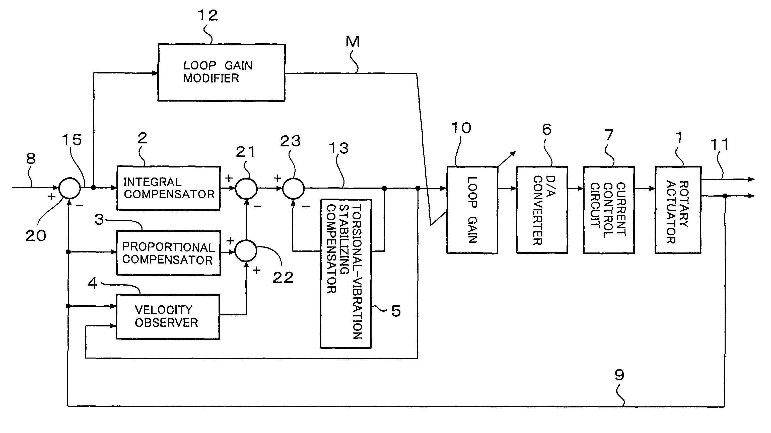
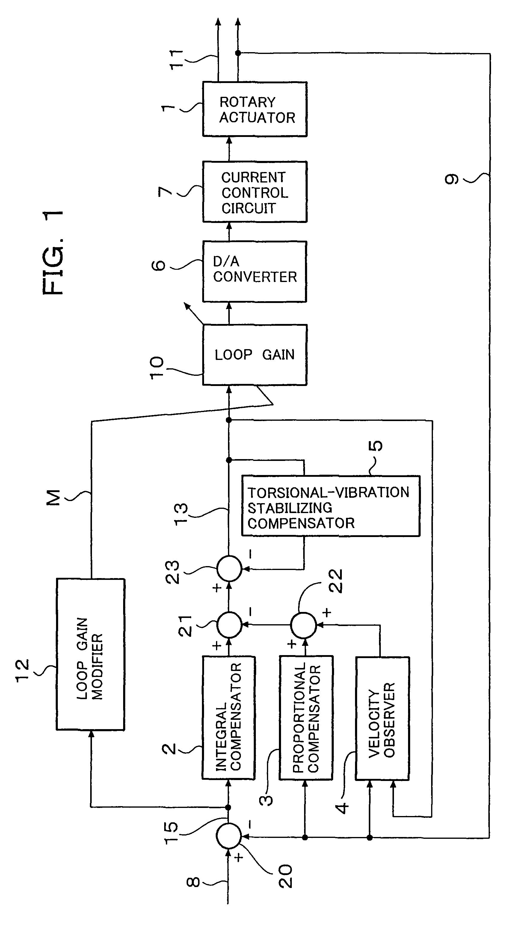
[0036]Referring first to FIG. 1, a steerable mirror control system according to Example 1 of the present invention will be described. This steerable mirror control system has been implemented as a digital control firmware making use of a microprocessor, the illustration of which is omitted in FIG. 1. Processings at an integral compensator 2, proportional compensator 3, velocity observer 4, torsional-vibration stabilizing compensator 5, loop gain 10, loop gain modifier 12 and adders 20,21,22,23 are described in parts of a program which the above-described microprocessor performs. At a discrete time in every constant sampling cycle (hereinafter called “the discrete time”), a processing operation is performed.

[0037]On a rotary actuator 1, a single steerable mirror (not shown) is mounted, and an angle of the steerable mirror is used as a controlled variable signal 11 in the steerable mirror control system. The rotary actuator 1 is also provided with a built-in rotary encoder (not shown)...

example 2

[0062]A description will next be made about a positioning control system for a moving element, which is equipped with a loop gain modifier capable of suppressing not only an overshoot but also an undershoot. It is to be noted that an illustration of a steerable mirror control system of Example 2 in a block diagram is omitted as the block diagram is substantially the same as FIG. 1.

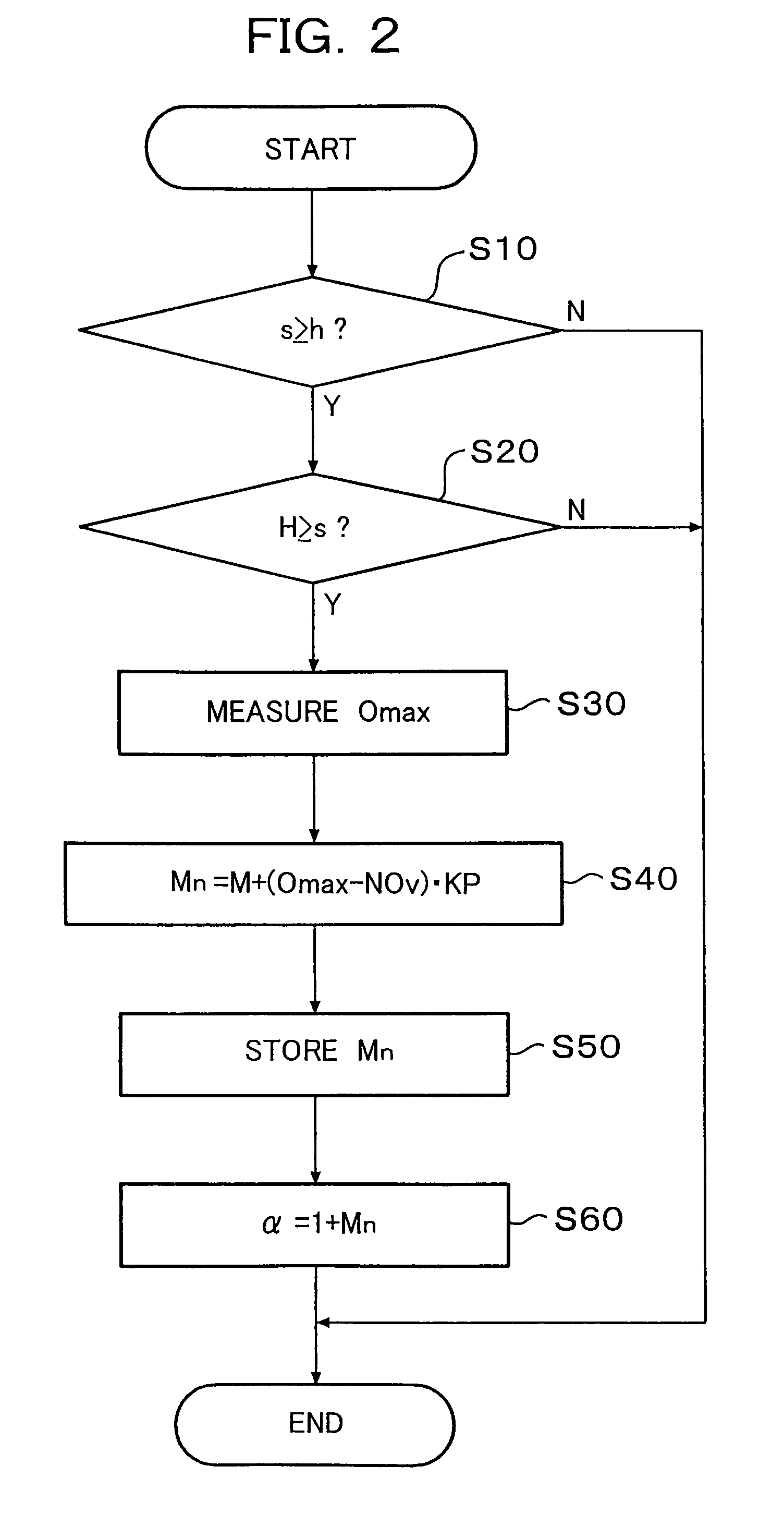
[0063]A loop gain modifier 12 of Example 2 is equipped, as in the loop gain modifier of Example 1, with a storage unit, timer unit, comparison unit, decision unit, computing unit and so on. In the storage unit, an amount NOv of nominal overshoot, an amount NUv of nominal undershoot, a coefficient KP and a correction value M are stored. The amount NOv of nominal overshoot and the amount NUv of nominal undershoot are an overshoot amount and an undershoot amount sufficient to meet a target specification, respectively. Assuming that the settling range of a setting response is ±W, these overshoot and undershoot...

example 3

[0073]With reference to FIG. 7, a description will next be made about a laser drilling machine for drilling a printed circuit board. The laser drilling machine is equipped with two steerable mirror control systems, which are similar to that described above in Example 1 or 2, as galvanometer scanner assemblies to perform modifications of loop gains, respectively.

[0074]A laser source 301 oscillates its laser to emit a laser beam. The emission of the laser beam is controlled by a command from a upper-level control. One of the galvanometer scanner assemblies, that is, a galvanometer scanner assembly 302 positions a steerable mirror 302a at an angle, which has been commanded by angle command data, to irradiate the laser beam onto a drilling position. The other galvanometer scanner assembly, that is, a galvanometer scanner assembly 303 positions a steerable mirror 303a at an angle, which has been commanded by angle command data, to emit the laser beam, which has been reflected at the stee...


PUM

PropertyMeasurementUnit
timeaaaaaaaaaa
Mnaaaaaaaaaa
distanceaaaaaaaaaa

Abstract

A positioning control system for positioning a moving element on a basis of position command data is provided with a feedback loop. The system is also provided with a loop gain modifier for determining a loop gain, which is to be used in a following positioning operation, on a basis of a difference between an amount of overshoot measured in a current positioning operation and a predetermined tolerance or on a basis of a difference between an amount of overshoot measured in a current positioning operation and a first predetermined tolerance and a difference between an amount of undershoot measured in the current positioning operation and a second predetermined tolerance. The first and second tolerances may preferably be the same in absolute value. The moving element may specifically be a steerable mirror for drilling holes in a work by reflecting a laser beam. Also disclosed is a laser drilling machine including the system.

Description

FIELD OF THE INVENTION[0001]This invention relates to a positioning control system for a moving element, which detects the position of the moving element and controls the moving element so that the moving element tracks designated target points, and also to a laser drilling machine capable of controlling a moving element by such positioning control system.DESCRIPTION OF THE RELATED ART[0002]High-speed and high-accuracy positioning systems for moving elements are widely used in industry, including precision machine tools, storage devices for computers, and semiconductor fabrication systems. For a laser drilling machine for performing drilling in a fabrication process of a printed circuit board, for example, a positioning control system is required to successively irradiating with a laser beam onto plural work positions on a work. A steerable mirror control system is often used to achieve high throughput and high-accuracy machining.[0003]In general, a laser drilling machine is a numer...

Claims


Application Information

Patent Timeline
Patent Type & Authority Patents(United States)
IPC IPC(8): B23K26/00G05B11/18G05B13/02G05B19/23B23K26/064B23K26/082G05D3/12
CPCG05B2219/41029G05B2219/45139G05B2219/41127G05B19/231
Inventor ONO, TAKASHITOYAMA, SOUICHIOKUBO, YAICHIHIRAI, HIROMU
Owner NAGOYA INSTITUTE OF TECHNOLOGY
Why Eureka
Try Eureka