Luminescent solar concentrator

a solar concentrator and solar energy technology, applied in the field of solar concentrators, can solve the problems of low light diffusion efficiency, poor light diffusion effect, and poor robustness of light concentrator optical elements, and achieve the effect of not being cheap, not very effective in diffuse light, and not being able to meet the requirements of light diffusion

Active Publication Date: 2014-11-18
EASTMAN KODAK CO
View PDF49 Cites 2 Cited by
  • Summary
  • Abstract
  • Description
  • Claims
  • Application Information

AI Technical Summary

Benefits of technology

[0031]The invention enables recapture of radiation that has escaped from radiation concentrator devices and more particularly from luminescent planar concentrators (LPC). It finds particular application in addressing the ‘reabsorption’ problem in which losses to an LPC system can arise due to the random nature of re-emission of radiation from luminescent dyes leading to up to 30% of re-emitted radiation escaping the device on each occasion. The invention enables the capture and retention within the device of a substantial proportion of that escaped radiation.

Problems solved by technology

Many PV cells, however, require for their manufacture materials that are expensive and energy-intensive to produce.
Whilst this approach has met with some success, the light concentrator optical elements, typically mirrors or lenses, need to be very robust and may not themselves be cheap items.
Furthermore, the greater the concentration ratio, the smaller is the acceptance angle to the concentrator with the result that high-concentration systems also have the disadvantage that they are required to track the sun for efficient concentration and also are not very effective in diffuse light (e.g. cloudy weather).
There are, however, several problems with this form of absorptive-emissive or luminescent radiation concentrator, associated with the difficulty in finding suitable fluorescent dyes as absorbing materials.
Typical organic fluorescent dyes having broad band absorption and emission have absorption and emission spectra which have significant levels of overlap, which results in re-absorption of emitted radiation.
Re-absorption of emitted radiation reduces the efficiency for at least two reasons: when the re-absorbed radiation is again re-emitted, the quantum yield of the absorption-emission process results in a small loss if it is not unity; and up to approximately a further 30% is lost by being re-emitted in a direction which avoids total internal reflection by the waveguide.
The latter loss arises because when re-emission occurs, the direction of propagation of the original light is lost and light is emitted in random directions resulting in the said further 30% loss of radiation from the system.
This mechanism is the greatest source of loss in an LPC and restricts the size (and therefore benefit) of planar concentrators.
Whilst the Stokes shift in principle reduces the risk of reabsorption and increases the mean free path of re-emitted radiation, there typically remains a degree of overlap which limits the size of the concentrator that is possible before reabsorption / re-emission losses become significant.
However, the disadvantages with this method are that the edge-mounted PV element is required to be three times the size (to cover three edges) and it is difficult to identify appropriate fluorescent dyes that absorb at different wavelengths but emit at the same narrow wavelength suitable for the PV element whilst meeting the other requirements of transparency, photo-stability, high Stokes shift, etc.
Whilst this solution assists in re-capturing incident radiation outside the spectrum of activation of the luminescent material contained within the waveguide, the luminescent material itself, which in the specific example is sulforhodamine 101 organic fluorescent dye, remains unsatisfactory for use in the waveguide in that there is insufficient separation between the absorption and emission spectra, which leads to an unsatisfactory overlap and significant re-absorption.
A further problem with fluorescent dye-based systems has been the tendency for the dye to degrade over time due to exposure to solar ultraviolet light, although some efforts to identify more stable fluorescent dyes have been made.
Whilst quantum dots possess the characteristic of suitable broad-band visible absorption and narrow band emission, they suffer from the common characteristic of small Stokes shift, which reduces the path length of emitted radiation due to re-absorption.

Method used


Image

  • Luminescent solar concentrator
  • Luminescent solar concentrator
  • Luminescent solar concentrator

Examples


example 1

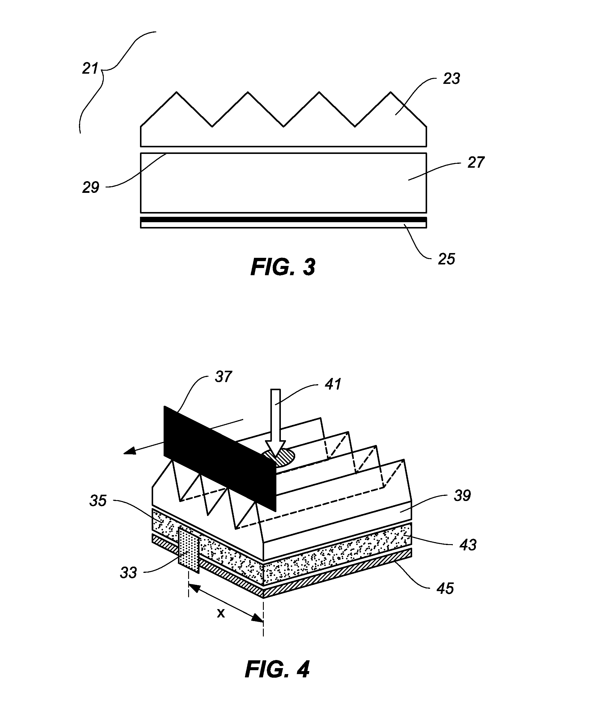
[0126]A 0.27 mm thick sheet of a flexible plastic doped with a luminescent Rhodamine dye was used as the luminescent concentrator sheet element. The sheet was approximately 20 cm square. A green LED with 250 mCd output and λmax of 563 nm was coupled to a microscope with objective diameter 5.24 mm to provide a collimated incident beam. The peak wavelength of the LED corresponded very closely to the spectral absorption peak of the luminescent dye used. The dye density was such that about one third of the incident green light was transmitted in the sheet on a single pass. A large area photodiode was baffled with black card to provide a square aperture 33 with 5 mm side and was brought close to the edge of the luminescent sheet to detect luminescent emission from its edge face 35 as shown in FIG. 4. A black card sheet 37 was used as a baffle to prevent stray light from entering the detector directly from the LED 31. The photocurrent was amplified and measured. The LED light source was p...

example 2

[0128]The thin plastic film doped with rhodamine dye was replaced by an A4 sized PMMA slab of thickness 3 mm doped with Lumogen™ F Red dye (BASF). Black adhesive tape was affixed to 3 side-faces of the sheet to stop edge reflections. It was noted that the use of the black tape reduced the signal at the maximum separation of LED and detector by about 10%. Again, as in Example 1, a mirror was placed below the luminescent sheet and a SOLF™ film was placed above. In this experiment, the green LED was moved and the detector held stationary to vary the distance D as shown in FIG. 5. A black baffle was placed between the LED and the detector to reduce stray light. The detector was a 100 mm2 photodiode supplied by Melles Griot which was itself unbaffled to receive light from both the luminescent sheet and from the “outer waveguide” comprising the mirror and the SOLF™ sheet.

[0129]FIG. 9 shows the results of this experiment where there is a clear benefit of using the prism sheet. The differen...


PUM


Abstract

A solar concentrator device comprising a solar concentrator element comprising a radiation transmissive surface, a radiation absorptive material and a radiation concentrating / collection point and disposed on the incident radiation side thereof a recapture element for recapturing at least a portion of radiation lost from the concentrator element has improved solar radiation collection efficiency by reintroducing recaptured radiation into the concentrator element or by propagating said recaptured radiation through the recapture element to a radiation concentration point associated with the recapture element. It has been found that planar elements having a grooved or corrugated outer surface make for very good recapture elements for planar concentrator elements.

Description

FIELD OF THE INVENTION[0001]This invention relates to the field of solar concentrators, especially for solar photovoltaic devices, and more particularly to planar concentrators such as luminescent planar concentrators (LPCs) and to methods for increasing the efficiency of LPCs.BACKGROUND OF THE INVENTION[0002]Photovoltaic cells are a means for converting incident radiation, typically actinic radiation such as solar radiation, into electrical energy. There is significant interest worldwide in the generation of power from sunlight. Radiation concentration is finding increasing relevance for the purpose of improving the efficiency or applicability of photovoltaic (PV) cells used for power generation for three reasons: first, because for some PV technologies, higher incident illumination intensity actually increases the efficiency of power conversion; second, because it is believed that for some applications, it may prove to be a more cost-effective approach for large area power generat...

Claims


Application Information

Patent Timeline
Patent Type & Authority Patents(United States)
IPC IPC(8): H01L31/055H01L31/052
CPCH01L31/0525H01L31/055Y02E10/52H01L31/0524G02B27/148H01L31/0547G02B19/0042G02B19/0019H01L31/0543H01L31/054H01L31/02322H01L31/052
Inventor RIDER, CHRISTOPHER, B.
Owner EASTMAN KODAK CO
Why Eureka
Try Eureka