
Catheter for intravascular ultrasound and photoacoustic imaging

a technology of intravascular ultrasound and photoacoustic imaging, applied in the direction of catheters, applications, ultrasonic/sonic/infrasonic image/data processing, etc., can solve the problems that catheters cannot be used for combined ivus, ivpa and elasticity imaging, radiation and/or acoustic therapy, etc., to prevent mechanical damage of the artery, reduce radiation loss, and high fluence

Inactive Publication Date: 2015-01-13
BOARD OF RGT THE UNIV OF TEXAS SYST
View PDF15 Cites 13 Cited by
  • Summary
  • Abstract
  • Description
  • Claims
  • Application Information

AI Technical Summary

Benefits of technology

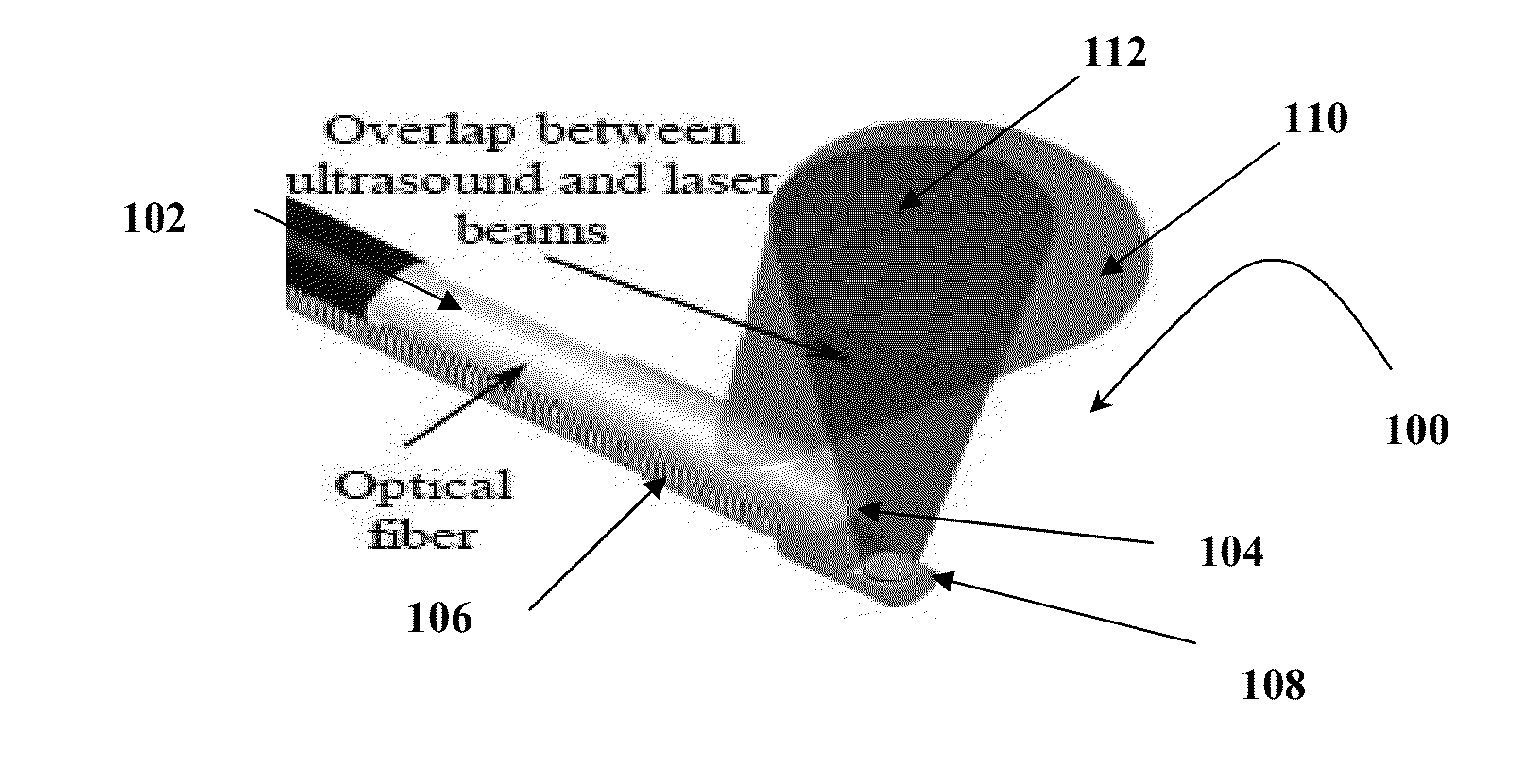
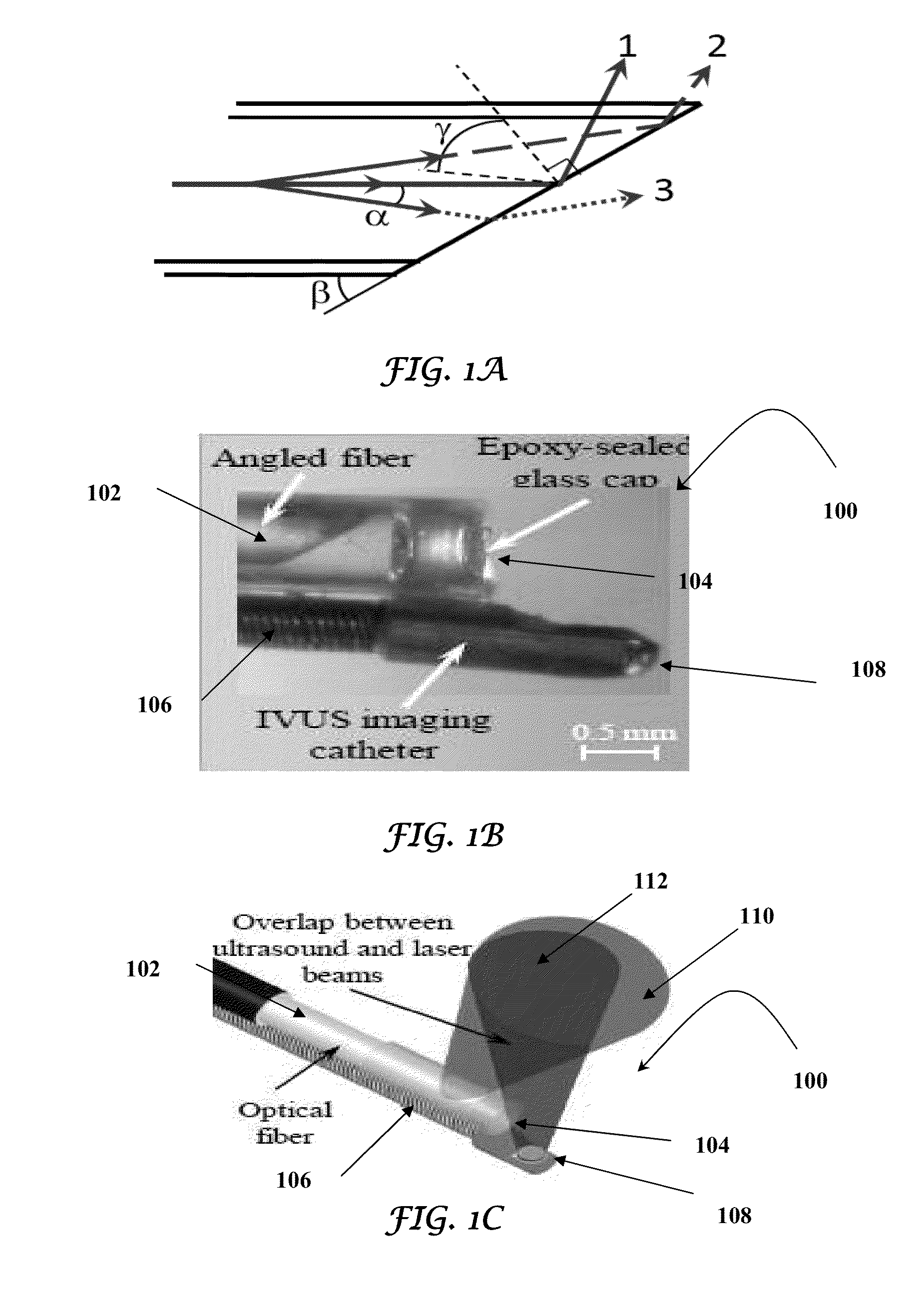
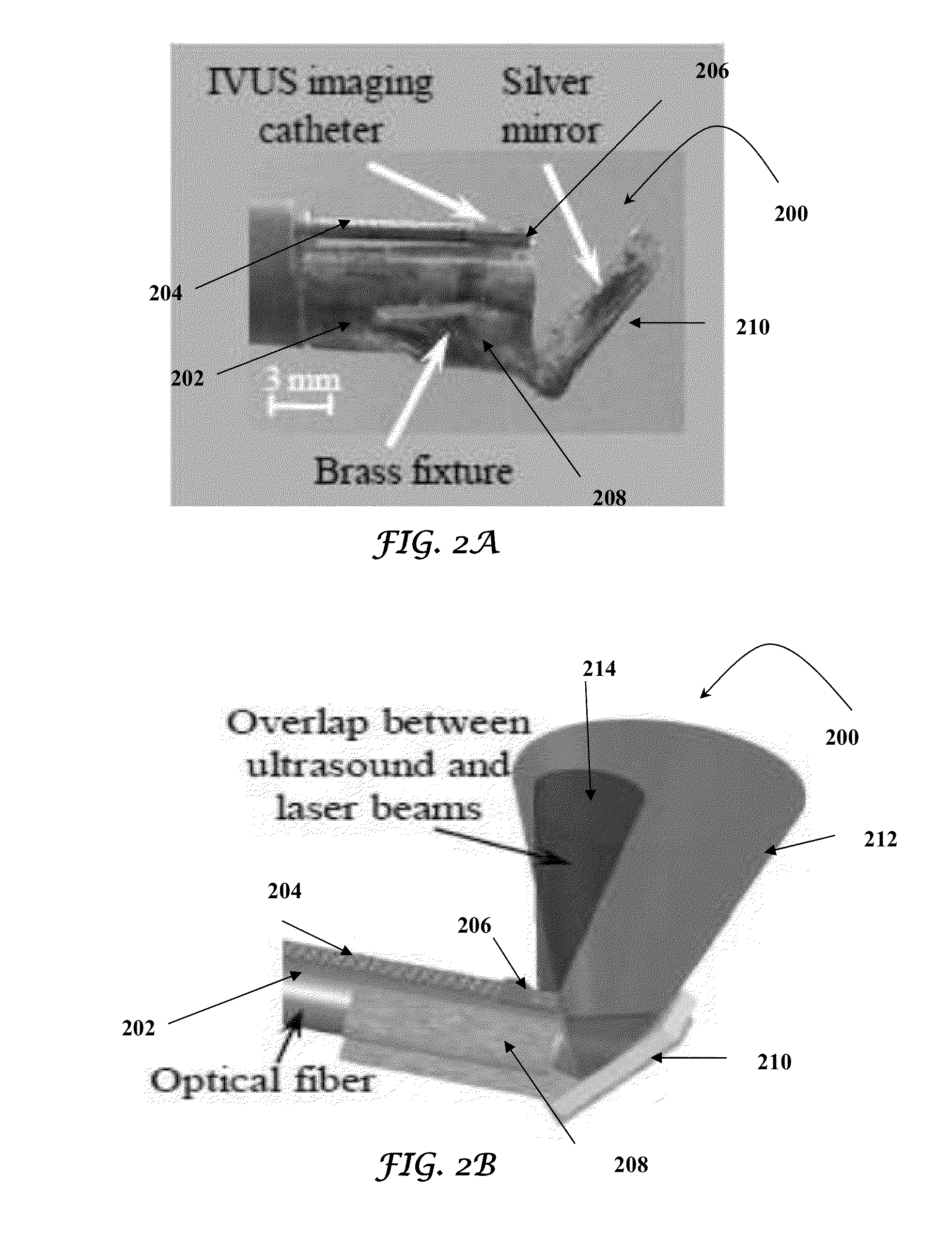
The present invention is a device that combines ultrasound imaging and therapy using optical fibers and light delivery systems. The device can be used to image and treat arteries with plaques and other abnormalities. The optical units can be rotated around the catheter's longitudinal axis to optimize the imaging and therapy. The device also includes a light-transparent tube to protect the artery and a fixture to concentrate the light in the area where ultrasound waves are propagated. The device can transmit ultrasound waves with high resolution and penetration depth. The duration of the pulses and the duty cycle of the ultrasound waves can be adjusted for acoustic therapy. The device also allows for varying the duration of the pulses and the duty cycle of the ultrasound waves as required for acoustic therapy. The light delivery system can use micro-optics or total internal effect to redirect light and create an optical contrast for the tissue. The device can be designed to provide maximum overlap between the ultrasound beams and the light beams emitted.

Problems solved by technology

Currently available catheters cannot be used both for combined IVUS, IVPA and elasticity imaging and for radiation and / or acoustic therapy.

Method used


Image

  • Catheter for intravascular ultrasound and photoacoustic imaging
  • Catheter for intravascular ultrasound and photoacoustic imaging
  • Catheter for intravascular ultrasound and photoacoustic imaging

Examples


Embodiment Construction

[0039]While the making and using of various embodiments of the present invention are discussed in detail below, it should be appreciated that the present invention provides many applicable inventive concepts that can be embodied in a wide variety of specific contexts. The specific embodiments discussed herein are merely illustrative of specific ways to make and use the invention and do not delimit the scope of the invention.

[0040]To facilitate the understanding of this invention, a number of terms are defined below. Terms defined herein have meanings as commonly understood by a person of ordinary skill in the areas relevant to the present invention. Terms such as “a”, “an” and “the” are not intended to refer to only a singular entity, but include the general class of which a specific example may be used for illustration. The terminology herein is used to describe specific embodiments of the invention, but their usage does not delimit the invention, except as outlined in the claims.

[...


PUM


Abstract

A design and a fabrication method for an intravascular imaging and therapeutic catheters for combined ultrasound, photoacoustic, and elasticity imaging and for optical and / or acoustic therapy of hollow organs and diseased blood vessels and tissues are disclosed in the present invention. The invention comprises both a device—optical fiber-based intravascular catheter designs for combined IVUS / IVPA, and elasticity imaging and for acoustic and / or optical therapy—and a method of combined ultrasound, photoacoustic, and elasticity imaging and optical and / or acoustic therapy. The designs of the catheters are based on single-element catheter-based ultrasound transducers or on ultrasound array-based units coupled with optical fiber, fiber bundles or a combination thereof with specially designed light delivery systems. One approach uses the side fire fiber, similar to the one utilized for biomedical optical spectroscopy. The second catheter design uses the micro-optics in the manner of a probe for optical coherent tomography.

Description

CROSS-REFERENCE TO RELATED APPLICATIONS[0001]This application is a National Stage of International Application No. PCT / US2010 / 055006, filed Nov. 1, 2010 which claims the benefit of U.S. Provisional Application No. 61 / 257,390, filed Nov. 2, 2009. The contents of each of which are incorporated by reference in their entirety.TECHNICAL FIELD OF THE INVENTION[0002]The present invention relates in general to the field of combined intravascular ultrasound, photoacoustic and elasticity imaging and intravascular radiation and / or acoustic therapy, and more particularly, to the design and fabrication of an intravascular catheter for combined intravascular ultrasound, photoacoustic and elasticity imaging and for intravascular radiation and / or acoustic therapy.BACKGROUND ART[0003]Without limiting the scope of the invention, its background is described in connection with the design and fabrication of an intravascular catheter that combines intravascular ultrasound, photoacoustic and elasticity im...

Claims


Application Information

Patent Timeline
Patent Type & Authority Patents(United States)
IPC IPC(8): A61B8/00A61B5/00A61B8/08A61B8/12
CPCA61B5/0095A61B8/0891A61B8/12A61B8/485A61B18/245
Inventor EMELIANOV, STANISLAVKARPIOUK, ANDREIWANG, BO
Owner BOARD OF RGT THE UNIV OF TEXAS SYST
Learn More