Master oscillator—power amplifier systems

a power amplifier and oscillator technology, applied in the field of fiberoptic light sources, can solve the problems of limited packaging options, low system efficiency, and inability to provide pump diodes with sufficient brightness to efficiently launch into the core, and achieve the effect of enhancing the absorption of pump light and low loss

Active Publication Date: 2015-02-03
LUMENTUM OPERATIONS LLC
View PDF20 Cites 25 Cited by
  • Summary
  • Abstract
  • Description
  • Claims
  • Application Information

AI Technical Summary

Benefits of technology

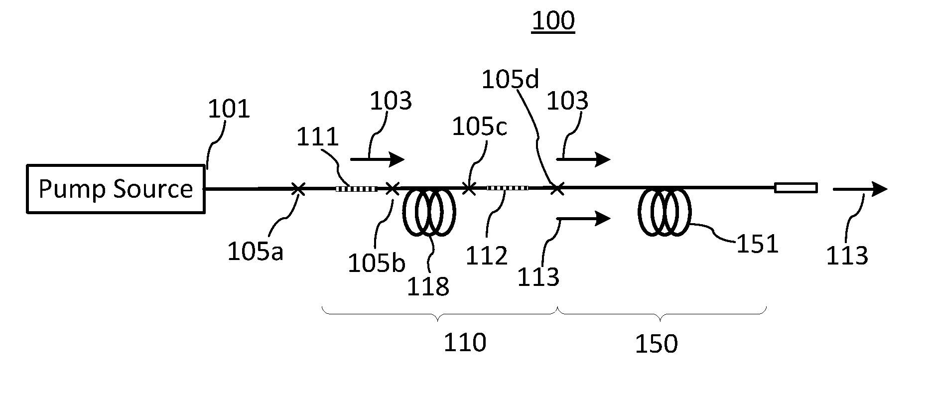
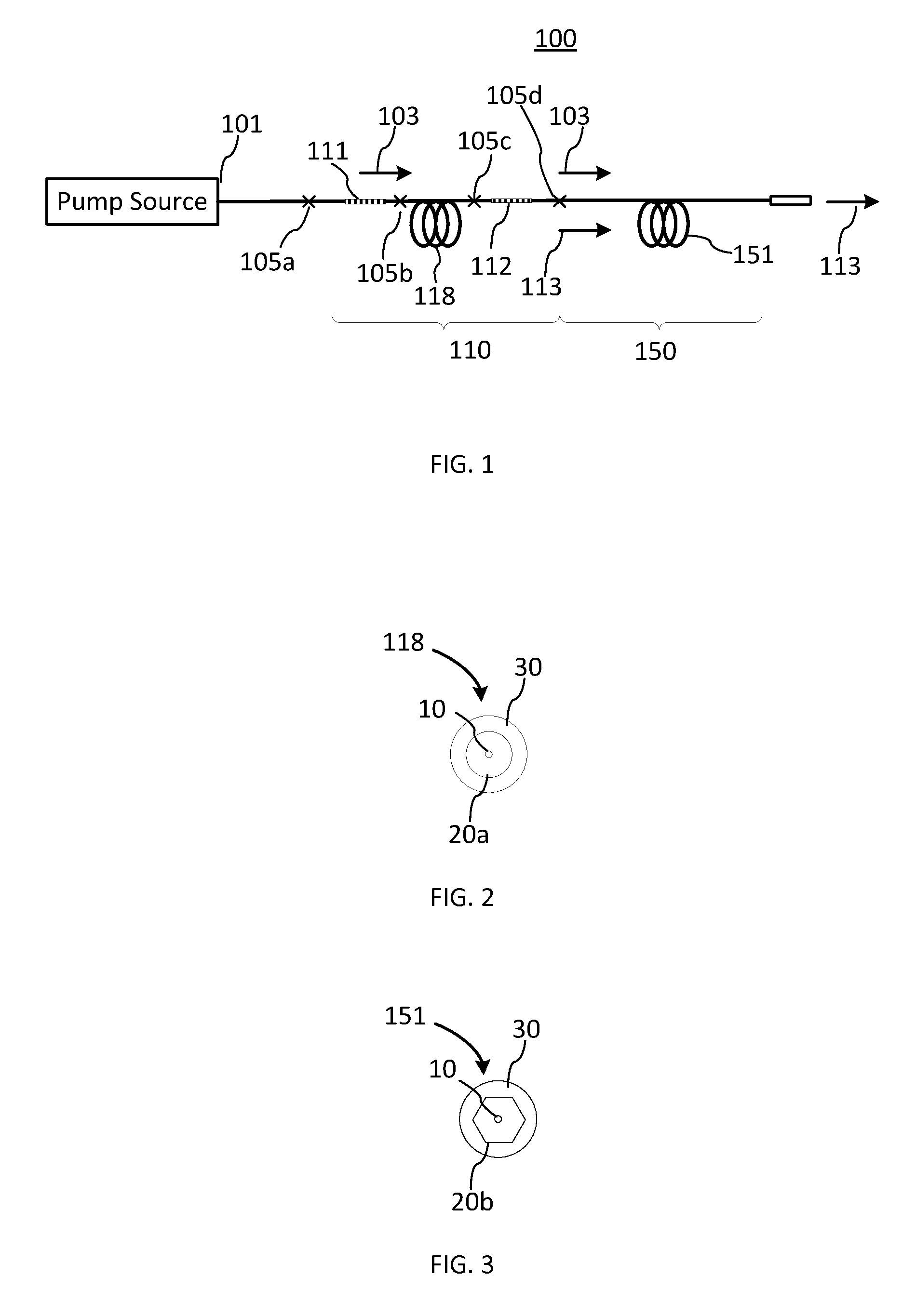
[0009]Accordingly, the present invention relates to an integrated master oscillator and power amplifier (MOPA) system comprising: a) a fiber laser oscillator for emitting laser light when pumped by pump light and comprising a first double clad optical fiber (DCF) having a core doped with active ions along at least a portion thereof, an inner cladding surrounding the core and defining a waveguide for the laser light generated in the core, and an outer cladding surrounding the inner cladding and defining a waveguide for the pump light, the fiber laser oscillator further including first and second fiber Bragg grating (FBG) reflectors integrally disposed at opposite ends of the first DCF so as to define an optical cavity of the fiber laser oscillator; b) a pump source optically coupled to the first DCF for emitting the pump light into the inner cladding of the first DCF; and, c) a first fiber optic power amplifier comprising a second double clad optical fiber having a core doped with active ions for amplifying the laser light received from the fiber laser oscillator through the second FBG reflector, an inner cladding for guiding the laser radiation, and an outer cladding for guiding the pump radiation received from the fiber laser oscillator through the second FBG reflector. The fiber laser oscillator is optically coupled to the first fiber optic amplifier using one or more optical splices so as to form a monolithic fiber-optic structure. The inner cladding of the first DCF has a circular cross-section in order to enable the formation of low loss optical splices in the integrated MOPA structure, while the inner cladding of the second double clad optical fiber has a shaped non-circular cross-section in order to enhance the absorption of the pump light in the doped core of the second DCF.
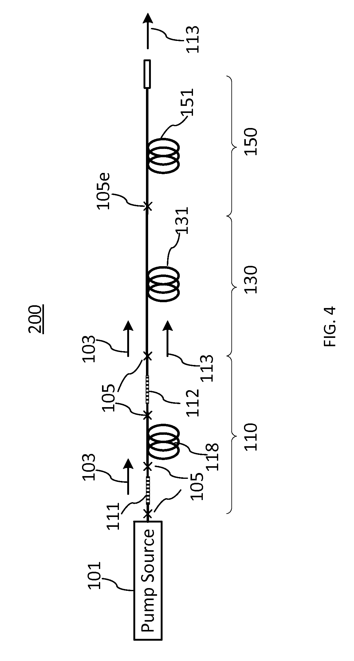
[0010]Another aspect of the present invention relates to an integrated MOPA system comprising a fiber laser oscillator comprising two fiber Bragg grating (FBG) reflectors spliced at opposite ends of a section of an amplifying optical fiber, an output power amplifier, and one or more intermediate fiber amplifiers sequentially coupled in-between the fiber laser oscillator and the output power amplifier using fiber-optic splices in the absence of mode mixers therebetween to form an integral fiber-optic structure, wherein each section of the MOPA system, including the fiber laser oscillator, the output amplifier and the one or more intermediate fiber amplifiers, is formed of a double-clad optical fiber (DCF) having a core, an inner cladding, and an outer cladding; and, wherein the inner cladding of the DCF has a circular cross-section in all sections of the MOPA system except for the output power amplifier where the inner cladding of the DCF has a shaped non-circular cross-section, in order to enhance the absorption of the pump light in a doped core of the output power amplifier while enabling the formation of low loss optical splices in the rest of the MOPA system.

Problems solved by technology

For higher-power fiber sources, pump diodes with sufficient brightness to efficiently launch into the core are not available.
In fact, in the absence of a mechanism to eliminate or scramble helical modes, a fraction of the pump light will not be absorbed even for extremely long fiber lengths, resulting in low system efficiency.
Another approach is to route the fiber in a non-circular path, such as a figure-eight, but this method limits packaging options and entails other compromises.
DCFs with shaped inner claddings, however, have certain practical disadvantages in comparison with more conventional circular-cladding fibers.
Firstly, the shaped-cladding fiber is more expensive because of the additional processing steps involved in fabricating the shaped preform used to draw the fiber.
These increased tolerances result in larger variability, both within a fiber run and lot-to-lot, in the pump loss when splicing to other fibers with matched cladding area, and in the pump absorption coefficient, which determines the optimum fiber length and / or the output power.
Furthermore, stripping, cleaving, and splicing of shaped fibers has lower yield and is less reproducible, increasing manufacturing times and scrap because of required rework.
Ultimately, higher pump and / or signal splice loss may be required to obtain acceptable yields or cycle times, resulting in lower system efficiency and problems associated with thermal management of the optical power lost in the splices, which is typically converted to heat.

Method used


Image

  • Master oscillator—power amplifier systems
  • Master oscillator—power amplifier systems
  • Master oscillator—power amplifier systems

Examples


Embodiment Construction

[0018]In the following description, for purposes of explanation and not limitation, specific details are set forth, such as particular optical designs, optical components, techniques, etc. in order to provide a thorough understanding of the present invention. However, it will be apparent to one skilled in the art that the present invention may be practiced in other embodiments that depart from these specific details. In other instances, detailed descriptions of well-known methods, devices, and circuits are omitted so as not to obscure the description of the present invention.

[0019]Note that as used herein, the terms “first”, “second” and so forth are not intended to imply sequential ordering, but rather are intended to distinguish one element from another unless explicitly stated. The term “double-clad optical fiber”, abbreviated as “DCF”, is used in this specification to refer to an optical fiber which has at least two waveguiding regions, one overlapping the other. “DCF” is unders...


PUM


Abstract

The invention provides fiber-optic light sources such as cladding-pumped master oscillator—power amplifier (MOPA) systems which use double-clad optical fibers (DCF). The inner cladding of the first DCF used in the master oscillator section has a circular cross-section in order to enable the formation of low loss optical splices in the integrated MOPA structure. The inner cladding of the second DCF in the output amplifier section has a shaped non-circular cross-section in order to enhance the absorption of the pump light in the doped core of the second DCF.

Description

CROSS-REFERENCE TO RELATED APPLICATIONS[0001]The present invention claims priority from U.S. Provisional Patent Application No. 61 / 646,665 filed May 14, 2012 which is incorporated herein by reference.TECHNICAL FIELD[0002]The present invention generally relates to fiber-optic light sources, and more particularly relates to master oscillator / power amplifier (MOPA) systems having circular cross-section of the inner cladding of the master oscillator double-clad optical fiber.BACKGROUND OF THE INVENTION[0003]Fiber-optic light sources using optical fibers doped with rare-earth ions such as erbium (Er) and ytterbium (Yb) are used in a variety of applications such as material processing, telecommunications, spectroscopy, medicine, etc. In a configuration commonly referred to as MOPA (Master Oscillator / Power Amplifier), a relatively low-power fiber laser with a desired spectral and temporal properties is used to seed one or more subsequent fiber-optic amplification stages, which boost the po...

Claims


Application Information

Patent Timeline
Patent Type & Authority Patents(United States)
IPC IPC(8): H01S3/23H01S3/067G02B6/02H01S3/094
CPCH01S3/2308G02B6/02371H01S3/06754H01S3/06733H01S3/06758H01S3/094007
Inventor KLINER, DAHVMUENDEL, MARTIN H.
Owner LUMENTUM OPERATIONS LLC
Why Eureka
Try Eureka