Surgical retractor

a retractor and surgical technology, applied in the field of surgical retractors, can solve the problems of deteriorating motor function of patients' extremities, affecting the performance of patients, and affecting the patient's extremities, so as to achieve the effect of improving performan

Active Publication Date: 2015-03-10
MENI MED
View PDF8 Cites 6 Cited by
  • Summary
  • Abstract
  • Description
  • Claims
  • Application Information

AI Technical Summary

Benefits of technology

[0031]The surgical retractor according to the present invention further improves the performance currently available with the prior art. It enables creating openings in the human body in locations in which the tissue pressure on its ribs is significantly more powerful than in brain surgery, such as in operations in close proximity with to the spine, with the ribs of the surgical retractor subject to pressure of the adjacent muscles.
[0032]An additional improvement is enabling the option of determining the shape of the opening in the operated body created by the surgical retractor when opening, and even changing the shape as necessary throughout the operation. This is achieved by a combination of opening all ribs of the surgical retractor simultaneously as a circle and subsequent individual control of each separate rib's inclination angle. Another major improvement is in enabling the replacement, prior to commencement of use of the surgical retractor, of the ribs of the surgical retractor without any need for any additional tools.
[0033]Yet another significant improvement is the addition of a light source to the surgical retractor, which grants the operating surgeon high visibility of the working area.
[0034]Yet another significant improvement is the addition of a video camera to the surgical retractor, which grants the operating surgeon high visibility of the working area.
[0050]According to still further features of an embodiment of the present invention the surgical retractor further includes: (f) at least two opening mechanism third type cog wheels, wherein each one of the least two opening mechanism third type cog wheels is mounted on another one of the bolt tails, wherein each one of the least two opening mechanism third type cog wheels has a opening mechanism third type cog wheel central hole having a non-circular cross section shape; and (g) an opening mechanism third type, for facilitating a uniform rotational movement opening of the ribs the opening mechanism third type is mounted on the least two opening mechanism third type cog wheels.

Problems solved by technology

Over traumatization (disruption of muscles and nerves roots) of soft tissues upon insertion of a retractor, in most cases hammering is required to insert the retractor between muscle fibrils, resulting in destruction and disruption of soft tissues.
During postoperative recovery, this kind of iatrogenic damage can inflict pain more severe than that caused by the pathology itself.
The tubular retractor frequently causes postoperative hemorrhaging and compression of the spinal cord, with motor function deterioration of the patient's extremities.
Uncontrolled soft tissue retraction (without measurement of retracted tissue pressure (RTP) and retracted tissue oxygen saturation (RTOS)) causes ischemic muscular degeneration-IMD and development of extremely rough postoperative scar tissue, resulting in circular compression of nerve roots and thus severe postoperative pain.
Very fast insertion of such tubular retractors causes splitting of muscles from vertebral bones and hemorrhaging.
Further, there may be confusion regarding anatomical structures in such a limited space.
Another problem is the limitations of effective decompression due to limited and constant (unchangeable, non-adjustable) diameters of tubular retractors.
Due to differing curvatures of vertebral lamina, tubular retractors don't enable the surgeon to approach lateral parts of lamina, including vertebral facets, and vision may be obstructed or disrupted by the use of tools in a narrow space with limited light.
Non-simultaneous unidirectional retraction of muscles causes uneven distribution of pressure to the soft tissues.
Uncontrolled soft tissue retraction (without measurement of retracted tissue pressure (RTP) and retracted tissue oxygen saturation (RTOS)) causes ischemic muscular degeneration (IMD), and development of extremely rough postoperative scar tissue, resulting in circular compression of nerve roots and thus severe postoperative pain.

Method used


Image

  • Surgical retractor
  • Surgical retractor
  • Surgical retractor

Examples


first embodiment

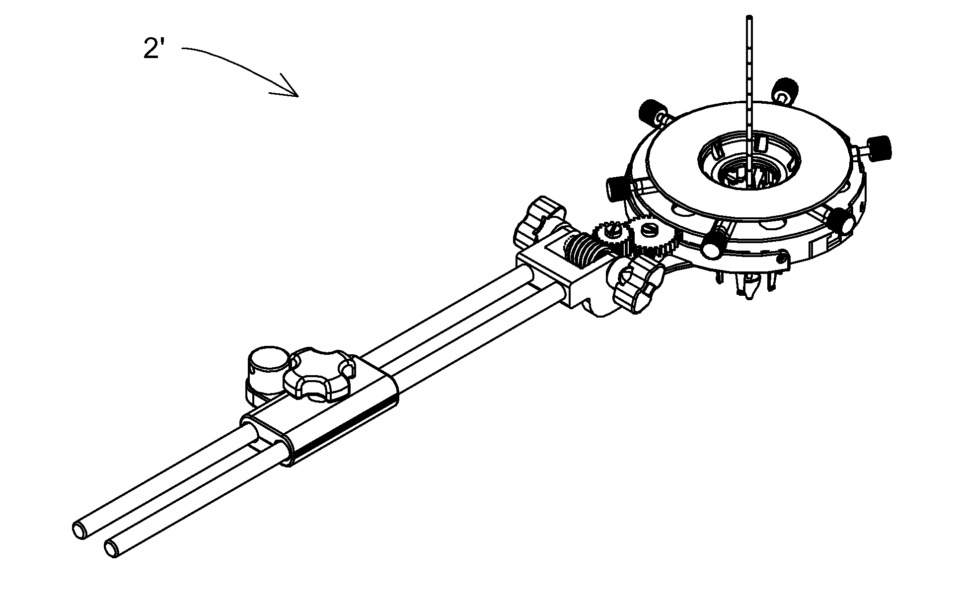
[0470]Referring now to the drawings, FIG. 2a, is an isometric side top view schematic illustration of a surgical retractor 2′ according to the present invention.

[0471]The surgical retractor 2′ is shown in an assembled state.

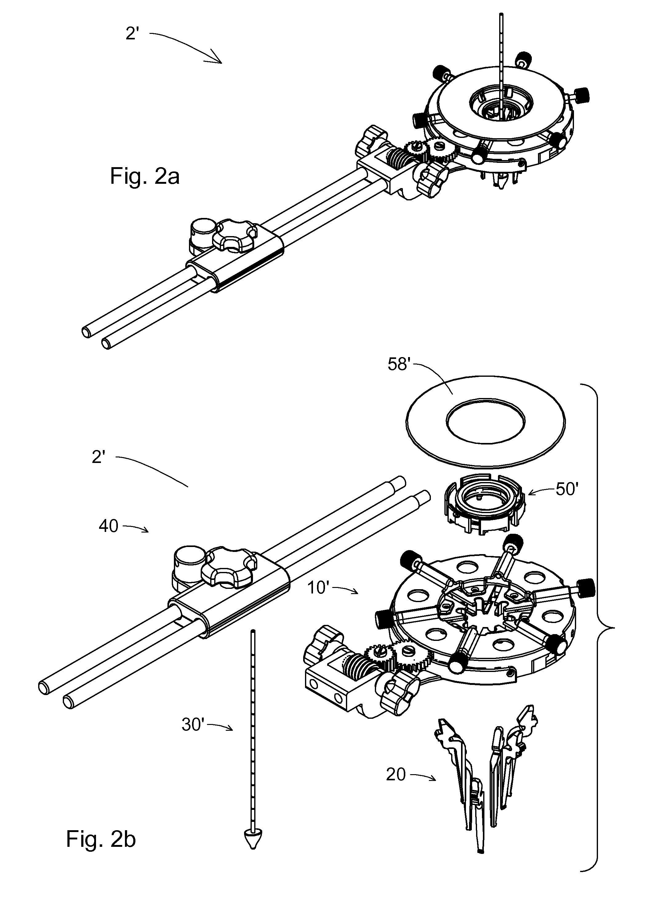
[0472]FIG. 2b, is exploded, isometric side top view schematic illustrations of a surgical retractor 2′, up to main assemblies, according to the first embodiment of the present invention.

[0473]The active assembly, which practically creates the opening in the operated patient's body for the purpose of performing the operation, is a ribs assembly 20, which can have an integrated central rod 30′, which leads the penetration into the body. The ribs assembly 20 has a wide range of opening states, which will be described in further detail in the following. These opening states are commanded and controlled by a mechanism for transferring of linear and rotational movements 10′. In addition, the surgical retractor 2′, according to the present invention, can include a light...

second embodiment

[0717]FIG. 29a is an isometric front top view schematic illustration of a surgical retractor 2″ according to the present invention.

[0718]This embodiment is simpler than the first embodiment. It includes less part, can be more lightweight, and can likewise be less expensive. As such, it can be suitable for single-time use, as a whole or the majority of its parts.

[0719]This embodiment includes the same ribs 21, for all features, as described so far according to the present invention. The ribs 21 of all the embodiments can be made of material or materials transparent to x-rays.

[0720]The channeled disc 13″ and the slider 15″ of the surgical retractor 2″ according to second embodiment differ in shape from the channeled disc 13″ and the slider 15″ of the surgical retractor 2′ according to first embodiment. However, in both embodiments, the sliders 15′, 15″ are assembled into channeled discs 13′, 13″ so as to enable linear radial movement relative to the centers channeled discs 13′, 13″.

[0...

third embodiment

[0797]FIG. 45a is a front view schematic illustration of a surgical retractor 2′″ according to the present invention.

[0798]The third embodiment includes, as will be further shown, mechanisms for generation of radial, linear, and angular movement of the ribs 21, similar to the mechanisms of the surgical retractor 2′ according to the first embodiment of the present invention, however the transmission 17′″ of the third embodiment is much simpler. Likewise, an auxiliary handle 59a is added to facilitate the insertion of the ribs 21 into the body of the operated patient.

[0799]The auxiliary handle 59a can be composed of metal and is removed from the surgical retractor 2′″ after insertion is completed.

[0800]FIG. 45b is an isometric top view schematic illustration of a surgical retractor 2′″ according to a third embodiment of the present invention.

[0801]The present illustration shows a wrench 59b (such as ratchet wrench) mounted on the surgical retractor 2′″. The wrench 59b serves for trans...


PUM


Abstract

A surgical retractor and a method of minimally invasive surgery, wherein the surgical retractor includes ribs and a mechanism for microns-resolution transferring of linear and rotational movements of the ribs and wherein each rib can be easily replaced without use of any additional tools.According to an embodiment of the present invention the transmission is simpler. Likewise, an auxiliary handle is added to facilitate the insertion of the ribs into the body of the operated patient, and the vast majority of components of the surgical retractor are made with biocompatible, and FDA approved material ULTEM HU 1000 RESIN transparent (radiolucent) to X-ray radiation and are designated for single use.

Description

REFERENCE TO CROSS-RELATED APPLICATION[0001]This application is a continuation-in-part of U.S. patent application Ser. No. 12 / 980,395, filed on Dec. 29, 2010, which is a continuation-in-part of U.S. patent application Ser. No. 12 / 880,162, filed on Sep. 13, 2010, which is a continuation-in-part of U.S. patent application Ser. No. 12 / 814,492, filed on Jun. 14, 2010, which claims priority from U.S. provisional patent application No. 61 / 307,469, filed on Feb. 24, 2010.[0002]This application claims priority benefits from U.S. patent application Ser. No. 12 / 980,395, filed on Dec. 29, 2010, herein incorporated by reference in its entirety, which claims priority from U.S. patent application Ser. No. 12 / 880,162, filed on Sep. 13, 2010, herein incorporated by reference in its entirety, which claims priority from U.S. patent application Ser. No. 12 / 814,492, filed on Jun. 14, 2010, herein incorporated by reference in its entirety, which claims priority from U.S. provisional application No. 61 / 3...

Claims


Application Information

Patent Timeline
Patent Type & Authority Patents(United States)
IPC IPC(8): A61B1/32A61B17/02A61B17/29
CPCA61B17/0293A61B2017/0256A61B2017/2936A61B2017/2943
Inventor MICHAELI, DAVIDMICHAELI, MICHAEL
Owner MENI MED
Why Eureka
Try Eureka