
Wireless communication device, wireless transmission system and wireless transmission method

a wireless transmission system and wireless communication technology, applied in the direction of multiple modulation transmitter/receiver arrangement, phase-modulated carrier system, sustainable building, etc., can solve the problems of large antenna size, interference between radio signal and baseband signal, and large size of antenna, so as to simplify the entire system configuration and reduce the circuit scale of the entire system

Active Publication Date: 2015-03-31
SONY CORP
View PDF20 Cites 8 Cited by
  • Summary
  • Abstract
  • Description
  • Claims
  • Application Information

AI Technical Summary

Benefits of technology

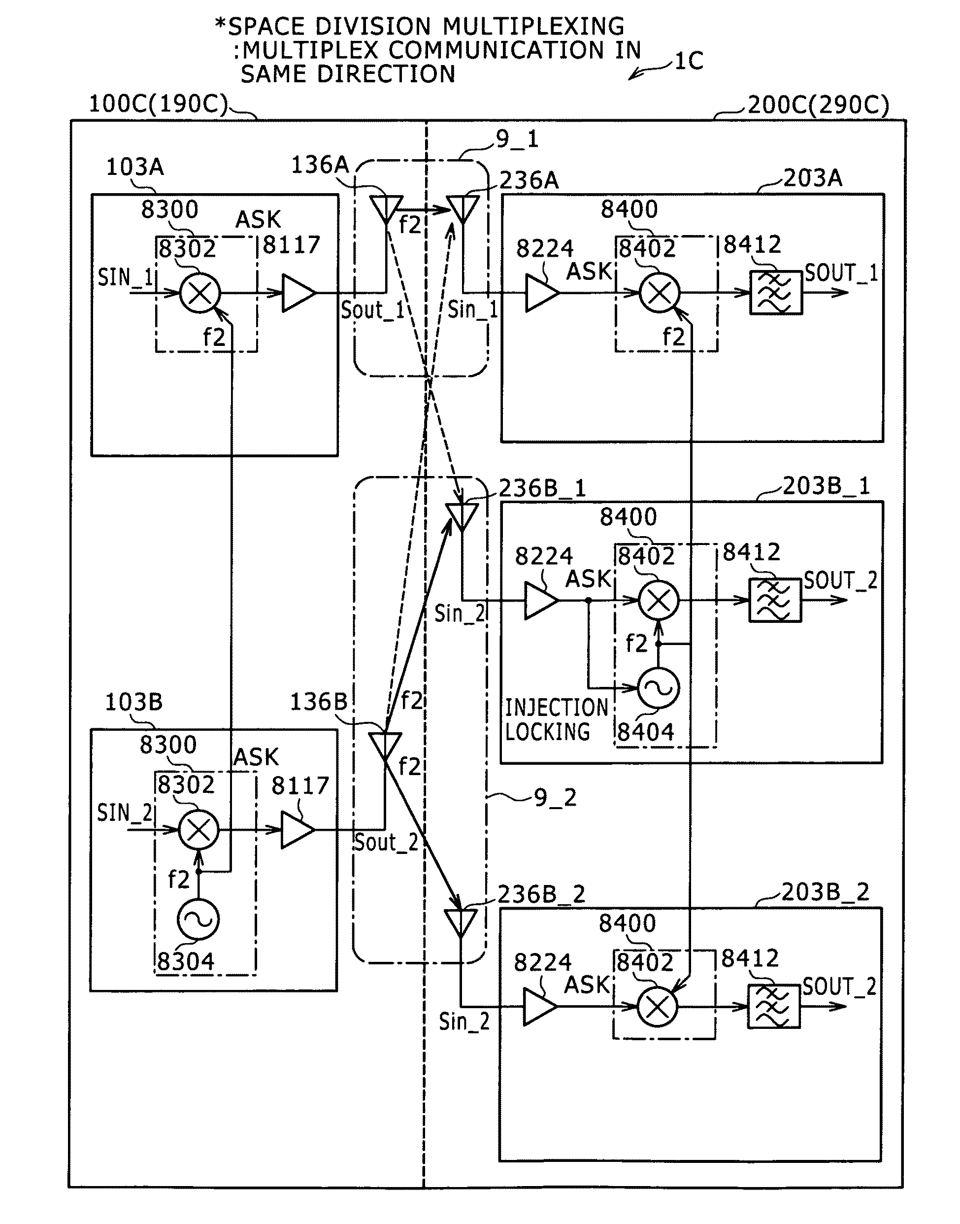
The present invention aims to reduce the circuit size of a wireless communication system by using a method called injection locking. This method allows for multiple communication pairs to communicate with each other using a single network. By reducing the number of communication pairs that require an injection locking circuit, the overall size of the system is reduced. The use of injection locking also results in a lower required transmission power and simplifies the circuit configuration. Additionally, the use of injection locking allows for proper demodulation of the transmission signal even if the stability of the carrier signal is reduced. This method also allows for the use of a simplified circuit configuration and simplifies the overall system design.

Problems solved by technology

However, such a as proposed in Patent Documents 1 and 2 uses such a low carrier frequency that it is not suitable for such high speed communication as transmission, for example, of an image signal and besides has a problem in regard to the size in that an antenna of a large size is required.
Further, since the frequency used for transmission is proximate to a frequency used in other baseband signal processing, there is a problem also in that interference is likely to occur between a radio signal and a baseband signal.
Further, where the carrier frequency is low, the communication is likely to be influenced by noise of a driving system in an apparatus, and a countermeasure is required.
This signifies that an oscillation circuit of a complicated circuit configuration having high frequency stability is required and that also the system configuration as a whole is complicated.
Further, where it is intended to implement an entire oscillation circuit including a tank circuit, which is a resonance circuit composed of an inductor and a capacitor, using a silicon integrated circuit, actually it is difficult to form a tank circuit having a high Q value.
Therefore, it cannot be avoided to dispose a tank circuit having a high Q value outside an integrated circuit.

Method used


Image

  • Wireless communication device, wireless transmission system and wireless transmission method
  • Wireless communication device, wireless transmission system and wireless transmission method
  • Wireless communication device, wireless transmission system and wireless transmission method

Examples


first example

[0421]FIGS. 33A to 33E show a product form of a first example to which the wireless transmission system 1 of the present embodiment is applied. The product form of the first example is an application where signal transmission is carried out using a millimeter wave in a housing of one electronic apparatus. The electronic apparatus in this instance is an image pickup apparatus which incorporates a solid-state image pickup device.

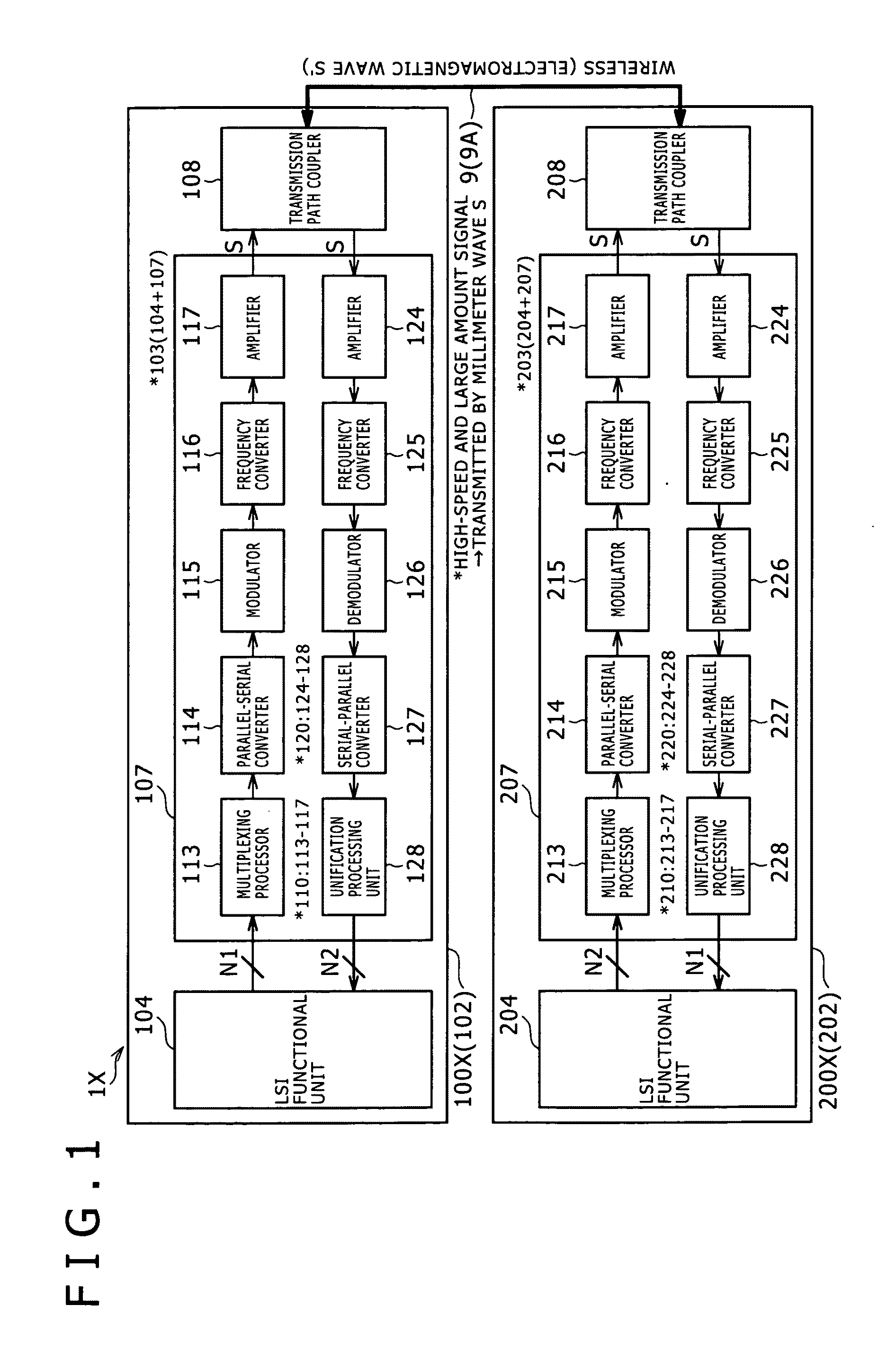
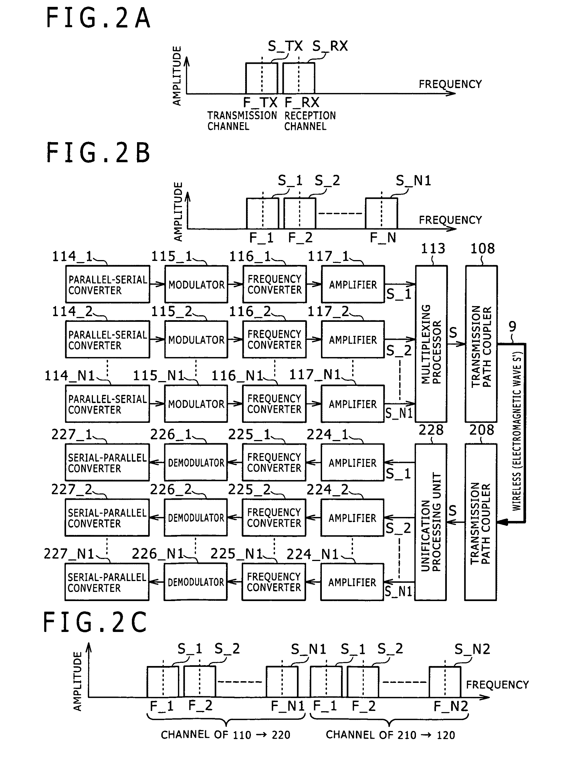
[0422]The first communication device 100 or the semiconductor chip 103 thereof is mounted on a main board 602 which carries out signal transmission to and from a image pickup board 502 on which a solid-state image pickup device 505 is incorporated, and the second communication device 200 or the semiconductor chip 203 thereof is mounted on the image pickup board 502. The signal generators 107 and 207 and transmission path couplers 108 and 208 are provided on the semiconductor chips 103 and 203, respectively.

[0423]The solid-state image pickup device 505 and the ...

second example

[0427]FIGS. 34A to 34C show a product form of a second example to which the wireless transmission system 1 of the present embodiment is applied. The product form of the second example is an application wherein signal transmission is carried out using a millimeter wave between a plurality of electronic apparatus which are in an integrated state. For example, one of the electronic apparatus may be mounted on the other electronic apparatus, for example, on the main frame side.

[0428]For example, a card type information processing device whose representative example is an IC card or a memory card in which a central processing unit (CPU), a nonvolatile memory device such as, for example, a flash memory and so forth are built is removably mounted on an electronic apparatus on the main frame side. The card type information processing device which is an example of a first electronic apparatus is hereinafter referred to also as “card type device,” and the other electronic apparatus on the mai...

third example

[0439]FIGS. 35A to 35C show a product form of a third example to which the wireless transmission system 1 of the present embodiment is applied, and particularly show an electronic apparatus of a modified form. Referring to FIGS. 35A to 35C, The wireless transmission system 1 includes a portable image reproduction apparatus 201K as an example of a first electronic apparatus and includes an image acquisition apparatus 101K as an example of a second electronic apparatus on the main frame side on which the image reproduction apparatus 201K is mounted. On the image acquisition apparatus 101K, a receiving table 5K on which the image reproduction apparatus 201K is to be mounted is provided at part of the housing 190. It is to be noted that the receiving table 5K may be replaced by the slot structure 4 as in the second example. The wireless transmission system 1 is similar to that of the product form of the second example in that signal transmission is carried out by wireless in the millime...


PUM


Abstract

Disclosed herein is a wireless communication device, including: a plurality of communication units for transmission adapted to modulate and transmit a transmission subject signal; the communication units for transmission including a communication unit or units for transmission which adopt a method which modulates the amplitude and a communication unit or units for transmission which adopt a modulation method which modulates at least the phase or the frequency and requires transmission power lower than that of the method which modulates the amplitude.

Description

BACKGROUND OF THE INVENTION[0001]1. Field of the Invention[0002]This invention relates to a wireless communication device, a wireless transmission system and a wireless communication method.[0003]2. Description of the Related Art[0004]As a technique for implementing a high-speed signal transmission between different electronic apparatus disposed in a comparatively short range (for example, within several centimeters to ten and several centimeters), or within an electronic apparatus, for example, a LVDS (Low Voltage Differential Signaling) is known. However, together with further increase of the amount of transmission information and further increase of the speed of transmission recently, increase of power consumption, increase of an influence of signal distortion by reflection and so forth, increase of unnecessary radiation and so forth have become problems. For example, the LVDS reaches a limit where a signal such as a video signal (including an image pickup signal), a computer ima...

Claims


Application Information

Patent Timeline
Patent Type & Authority Patents(United States)
IPC IPC(8): H04B1/66H04L27/02H04L27/18
CPCH04L27/02H04L27/18Y02B60/50H04L27/0008
Inventor MIHOTA, NORIHITO
Owner SONY CORP
Learn More