
Naphthalene derivative, organic material including the same, and organic electroluminescent device including the same

a technology of organic materials and derivatives, applied in the field of display, can solve the problems that compounds cannot be prevented from crystallizing, and achieve the effects of low driving voltage, excellent color purity, and high luminous efficiency

Inactive Publication Date: 2015-05-05
DAEJOO ELECTRONICS MATERIALS CO LTD
View PDF17 Cites 1 Cited by
  • Summary
  • Abstract
  • Description
  • Claims
  • Application Information

AI Technical Summary

Benefits of technology

[0008]It is an object of the present invention to provide an aromatic compound capable of achieving a low driving voltage, excellent color purity, high luminous efficiency, high heat resistance and a long lifetime, a material for an organic electroluminescent device, which includes the same, and an organic electroluminescent device including the same.
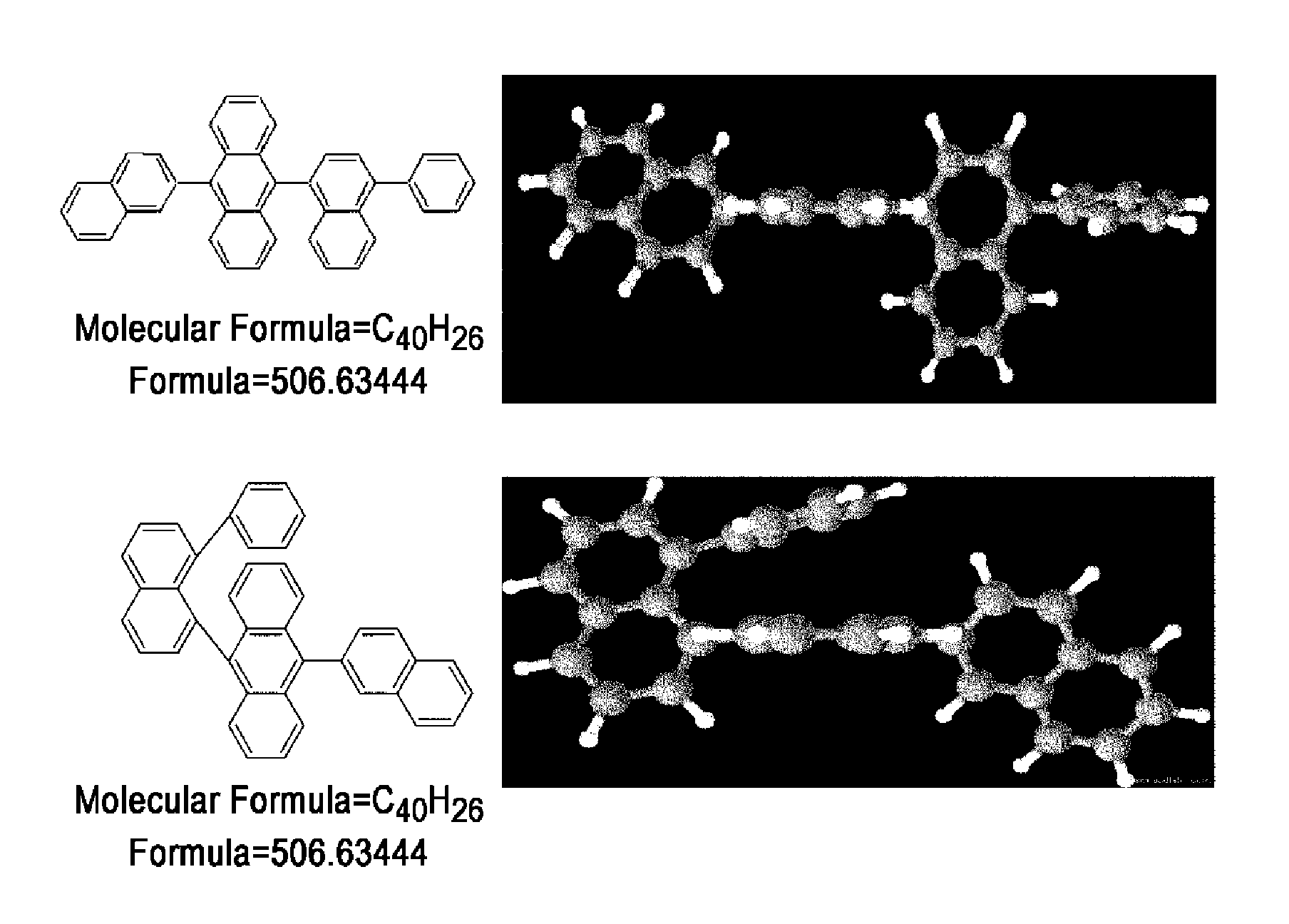
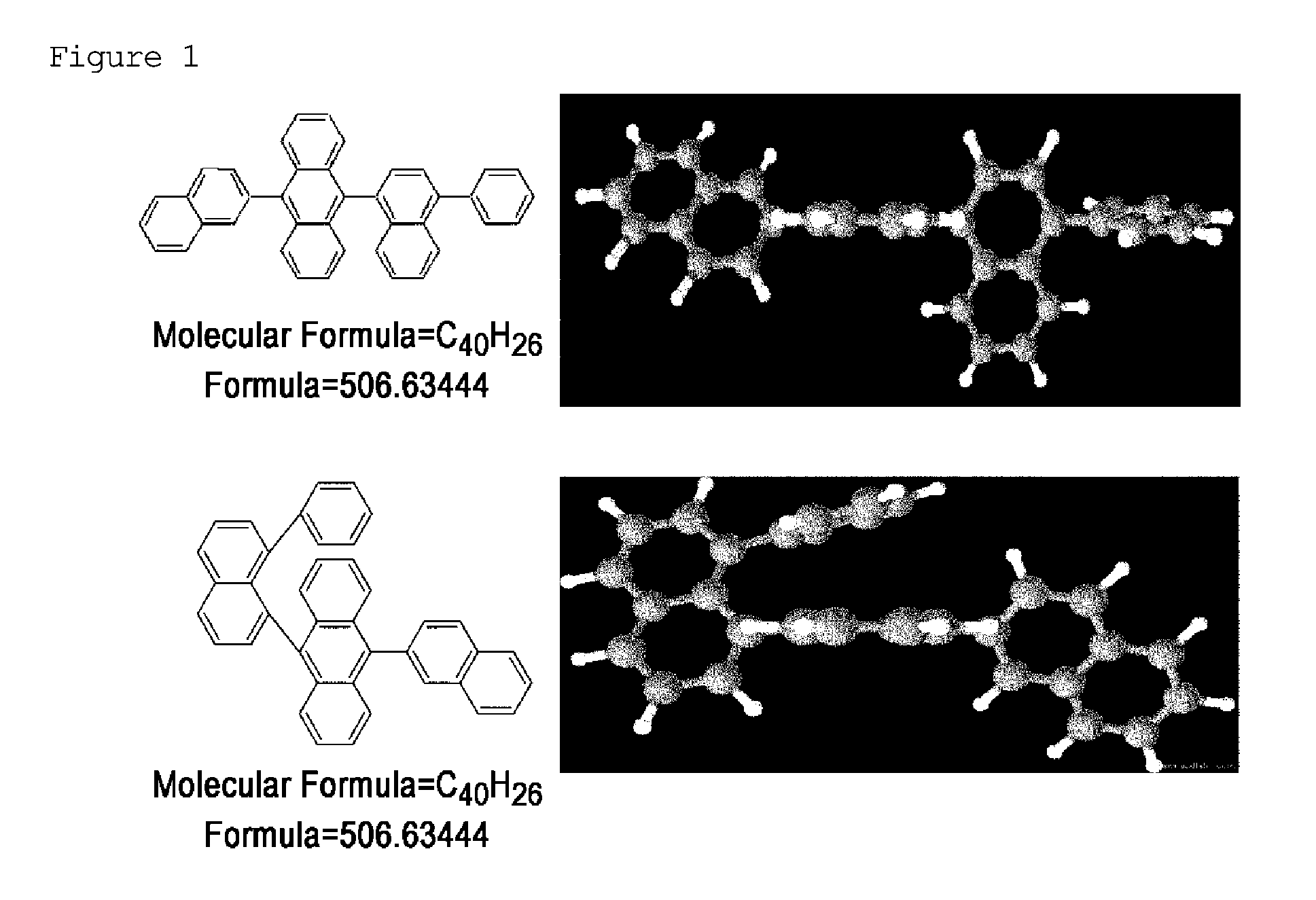
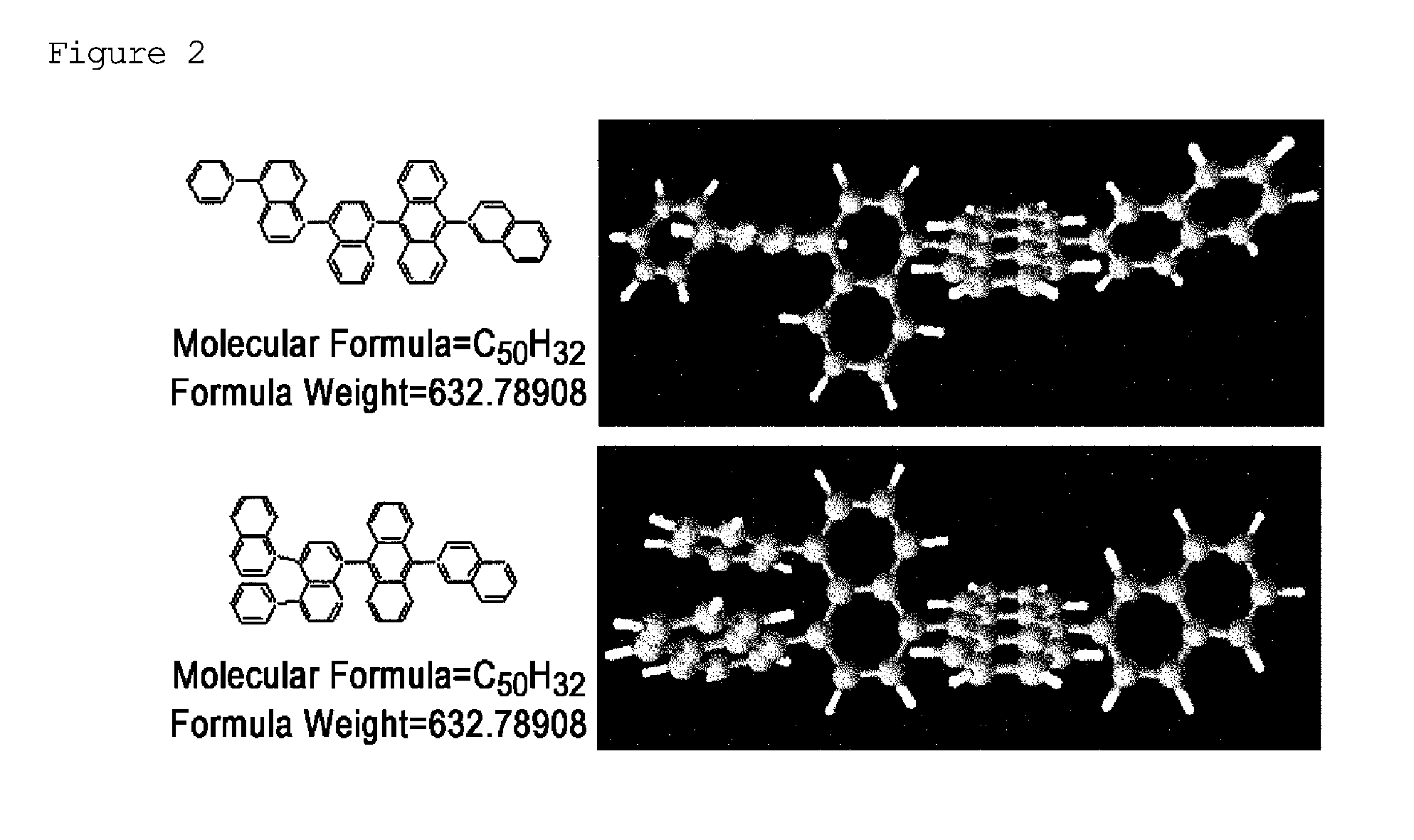
[0017]The compound of formula 1 is characterized in that it has substituents at the 1,8-positions of naphthalene and in that the chemical structure thereof is significantly distorted by a steric effect because the distance between the substituents is close. As shown in FIGS. 1 and 2, two kinds of compounds have the same molecular formula, but the three-dimensional steric structure of 1,8-substituted naphthalene is significantly distorted compared to that of 1,4-substituted naphthalene. Due to the distorted steric structure, the intermolecular spatial distance can be increased, and when this compound is applied to an organic electroluminescent device, the device can have excellent color purity and a long lifetime.
[0052]The present invention also provides a material for an organic electroluminescent device, which comprises the compound represented by formula 1. The compound represented by formula 1 may be used as a hole injection material, a hole transport material, a light-emitting material, an electron transport material and an electron injection material in an organic electroluminescent device, depending on the kind of substituents and characteristics thereof. In particular, the compound represented by formula 1 can be used as a host or dopant material for a light-emitting layer, and when it is used in a device, it can improve the driving voltage, thermal stability, lifetime, color purity and luminous efficiency of the device.
[0055]The organic electroluminescent device having a multilayer structure has an advantage in that a decrease in luminance or lifetime due to quenching can be prevented or a voltage that is applied thereto can be lowered. A layer into which holes are injected from an anode is referred to as “hole-injecting layer”, and a layer for receiving holes from the hole-injecting layer and transporting the holes to a light-emitting layer is referred to as “hole-transporting layer”, and an electron blocking layer for blocking the movement of an electron to the hole-transporting layer may also be formed between the organic light-emitting layer and the hole-transporting layer. If necessary, a material capable of performing both the injection and transport of holes may be selected so that the hole-injecting layer and the hole-transporting layer are not individually formed. Similarly, a layer into which electrons are injected from a cathode is referred to as “electron-injecting layer”, and a layer for receiving electrons from the electron-injecting layer and transporting the electrons to the light-emitting layer is referred to as “electron-transporting layer”. In addition, a hole blocking layer for blocking the movement of a hole to the electron-transporting layer may also be formed between the organic light-emitting layer and the electron-transporting layer. The light-emitting layer is a layer that emits light by recombination of a hole and an electron and may be composed of a single material or 2 to 5 different materials. When the light-emitting layer is composed of two or more different materials, the light-emitting materials are referred to according to their role. Specifically, the main constituent material of the light-emitting layer is referred to as “host”, and other material(s) is referred to as “dopant”.
[0062]The material of the hole-injecting layer is a material functioning to inject a plurality of holes from the anode in an applied electric field, and the hole-injecting layer is formed if the interfacial tension between the anode and the hole-transporting layer is not sufficiently high or if the work function of the anode significantly differs from the highest occupied molecular orbital (HOMO) of a layer adjacent thereto. The hole-injecting layer efficiently lowers the potential barrier of hole injection, and as a result, reduces the driving voltage of the organic electroluminescent device. Thus, the hole-injecting layer should be formed of a compound which has the ability to transport holes, has high efficiency with which holes are injected from the anode, maintains a stable interface with the anode, and essentially has excellent thermal stability. Thus, the hole-injecting layer may be made of the inventive compound represented by formula 1 or an already known material. Examples of the known material include, but are not limited to, a phthalocyanine derivative, a naphthalocyanine derivative, a porphyrin derivative, oxazole, oxadiazole, triazole, imidazole, imidazolone, imidazolethione, pyrazoline, pyrazolone, tetrahydroimidazole, hydrazone, acylhydrazone, polyarylalkane, stilbene, butadiene, benzidine type triphenylamine, styrylamine type triphenylamine, diamine type triphenylamine, derivatives thereof, and polymer materials such as polyvinyl carbazole, polysilane, and a conductive polymer (PEDOT / PSS). Of hole-injecting materials that may be used in the organic electroluminescent device of the present invention, a more effective hole-injecting material is an aromatic tertiary amine derivative or a phthalocyanine derivative. Specific examples of the aromatic tertiary amine derivative include, but are not limited to, triphenylamine, tritolylamine, tolyldiphenylamine, N,N′-diphenyl-N,N′-(3-methylphenyl)-1,1′-biphenyl-4,4′-diamine, N,N′,N′,N′-(4-methylphenyl)-1,1′-phenyl-4,4′-diamine, N,N,N′,N′-(4-methylphenyl)-1,1′-biphenyl-4,4′-diamine, N,N′-diphenyl-N,N′-dinaphthyl-1,1′-biphenyl-4,4′-diamine, 4,4′-bis{N-[4-(N,N-di-m-tolylamino)phenyl]-N-phenylamino}biphenyl, N,N′-biphenyl-N,N′-bis-[4-(phenyl-m-tolyl-amino)-phenyl]-biphenyl-4,4′-diamine, N,N′-(methylphenyl)-N,N′-(4-n-butylphenyl)phenanthrene-9,10-diamine, N,N-bis(4-di-4-tolylaminophenyl)-4-phenylcyclohexane, and an oligomer or polymer having the aromatic tertiary amine skeleton. Specific examples of the phthalocyanine (Pc) derivative include, but are not limited to, phthalocyanine derivatives such as H2Pc, CuPc, CoPc, NiPc, ZnPc, PdPc, FePc, MnPc, ClAlPc, ClGaPc, ClInPc, ClSnPc, Cl2SiPc, (HO)AlPc, (HO)GaPc, VOPc, TiOPc, MoOPc, GaPc-O—GaPc, and naphthalocyanine derivatives.
[0067]In order to increase the stability and lifetime of the inventive organic electroluminescent device against a temperature and humidity atmosphere, a protective layer may be formed on the surface of the device, or the device may be protected by coating with silicone oil or resin.

Problems solved by technology

Meanwhile, the stability of thin films has been required to increase the lifetime of devices, and improvement in conventional anthracene derivatives has been required, because these derivatives are frequently crystallized so that thin films including these derivatives are broken.
In addition, Japanese Patent Laid-Open Publication No. 2000-273056 discloses a horizontally asymmetrical allyl anthracene compound, but this compound cannot be prevented from being crystallized, because a group that is substituted with anthracenediyl is a simple phenyl or biphenyl group.

Method used


Image

  • Naphthalene derivative, organic material including the same, and organic electroluminescent device including the same
  • Naphthalene derivative, organic material including the same, and organic electroluminescent device including the same
  • Naphthalene derivative, organic material including the same, and organic electroluminescent device including the same

Examples


example 1

[0079]A compound of Example 1 was prepared according to the following preparation method.

[0080]

Step 1: Preparation of Intermediate 1-1

[0081]2,6-dibromonaphthalene (50 g, 170 mmol), phenylboronic acid (23 g, 190 mmol) and tetrakis(triphenylphosphine)palladium(0) (6.1 g, 10 mmol) were dissolved in 500 mL of tetrahydrofuran, and 260 mL of a 2N aqueous solution of potassium carbonate was added thereto. Then, the mixture was allowed to react under reflux for 24 hours. After completion of the reaction, the reaction solution was extracted with ethyl acetate, and the organic layer was dried using anhydrous magnesium sulfate, and then purified through a hexane column, thereby obtaining intermediate 1-1 at a yield of 75% (37 g).

Step 2: Preparation of Intermediate 1-2

[0082]Intermediate 1-1 (50 g, 180 mmol) was dissolved in 1000 mL of tetrahydrofuran under an argon atmosphere, and 1.6 M n-butyl lithium (121 mL) was added thereto at −78° C., followed by stirring for about 1 hour. At the same tem...

example 2

[0085]The following compound was prepared in the same manner as described in Example 1, except that 1,6′-binaphthyl-2′-ylboronic acid was used instead of intermediate 1-2.

[0086]

[0087]1H NMR (200 MHz, CDCl3): d 7.28-7.32 (t, 2H), 7.43-7.46 (t, 2H), 7.57-7.71 (m, 18H), 7.88-7.93 (m, 4H), 8.40-8.46 (m, 4H), 8.50-8.56 (m, 2H)

example 3

[0088]A compound of Example 3 was prepared according to the following method.

[0089]

Step 1: Preparation of Intermediate 3-1

[0090]1,8-dibromonaphthalene (50 g, 170 mmol), phenylboronic acid (23 g, 190 mmol) and tetrakis(triphenylphosphine)palladium(0) (6.1 g, 10 mmol) were dissolved in 500 mL of tetrahydrofuran, and 260 mL of a 2N aqueous solution of potassium carbonate was added thereto. Then, the mixture was allowed to react under reflux for 24 hours. After completion of the reaction, the reaction solution was extracted with ethyl acetate, and the organic layer was dried using anhydrous magnesium sulfate, and then purified through a hexane column, thereby obtaining intermediate 3-1 at a yield 63% (31 g).

Step 2: Preparation of Intermediate 3-2

[0091]9-bromoanthracene (50 g, 190 mmol), phenylboronic acid (31 g, 250 mmol) and tetrakis(triphenylphosphine)palladium(0) (6.7 g, 10 mmol) were dissolved in 1000 mL of tetrahydrofuran, and 291 mL of a 2N aqueous solution of potassium carbonate ...


PUM

PropertyMeasurementUnit
work functionaaaaaaaaaa
thicknessaaaaaaaaaa
thicknessaaaaaaaaaa

Abstract

The present invention provides a compound represented by the following formula 1. The compound of the present invention has high luminance, high luminous efficiency, excellent color purity and excellent high-temperature stability, and thus can provide a material for an organic electroluminescent device and an organic electroluminescent device having a long lifetime.

Description

RELATED APPLICATIONS[0001]This application is a National Phase of PCT Patent Application No. PCT / KR2012 / 002322 having International filing date of Mar. 29, 2012, which claims the benefit of priority of Korean Patent Application Nos. 10 2011 0027970 filed on Mar. 29, 2011 and 10-2011-0027969 filed on Mar. 29, 2011. The contents of the above applications are all incorporated by reference as if fully set forth herein in their entirety.FIELD AND BACKGROUND OF THE INVENTION[0002]The present invention relates to the display field, and more particularly to a naphthalene derivative that can be used in the preparation of an organic electroluminescent device that is a kind of display, a material for an organic electroluminescent device, which includes the same, and an organic electroluminescent device including the same.[0003]Organic semiconductors have been developed for application to various kinds of many electronic systems. Organic electroluminescent devices have a simple structure, vario...

Claims


Application Information

Patent Timeline
Patent Type & Authority Patents(United States)
IPC IPC(8): H01L51/00C07C15/28C09K11/06H01L51/50H05B33/10
CPCH01L51/5056H01L51/0052H01L51/0054H01L51/0058H01L51/5012C07C15/28C09K11/06H05B33/10H01L51/5072H01L51/5088H01L51/5092C09K2211/1007C09K2211/1011C07C2103/24C07C2603/24H10K85/622H10K85/626H10K85/615H10K50/11H10K50/17H10K50/15H10K50/16H10K50/171
Inventor JEON, YOUNG MINLEE, CHANG HYUNGPARK, JEONG GYUNAM, SANG JINMIN, HYO JINKIM, JOON WOOLIM, IL JI
Owner DAEJOO ELECTRONICS MATERIALS CO LTD
Learn More