Construction machine

a construction machine and construction technology, applied in mechanical machines/dredgers, machines/engines, transportation and packaging, etc., can solve the problems of reducing the volume affecting the work efficiency of workers, and affecting the use of the original toolbox, so as to achieve the effect of large work spa

Inactive Publication Date: 2015-05-12
NIHON KENKI CO LTD
View PDF22 Cites 24 Cited by
  • Summary
  • Abstract
  • Description
  • Claims
  • Application Information

AI Technical Summary

Benefits of technology

[0011]In view of the above-discussed problems with the conventional art, it is an object of the present invention to provide a construction machine in which a urea water tank can be mounted by effectively using a small space on the upper revolving structure.
[0024]With this arrangement, since the outer side plate covering the accommodating space is formed as the opening / closing cover, by opening the opening / closing cover, the urea water tank arranged on the inner surface thereof can be moved to the outside, and a water supply work to the urea water tank can be performed easily. Moreover, in a state where the opening / closing cover is set at the open state and the urea water tank is moved to the outside of the accommodating space, a large work space can be ensured in the accommodating space, and the maintenance work and the like for the control valve unit can be performed easily.

Problems solved by technology

Since the conventional art according to the above described Patent Document 1 is configured such that the urea water tank is accommodated in a toolbox, incase the tank volume is increased, the volume of the original toolbox is reduced, and there is a problem that a space for accommodating the tools, consumables and the like is made smaller.
If a urea water tank is accommodated in a toolbox, it is concerned that an access to the urea water tank might be obstructed by tools and the like in the toolbox, and labor might be required for a supply work to the urea water tank, which is a problem.
Since this rear small-revolving type hydraulic excavator has its upper revolving structure made as compact as possible in order to reduce the revolving radius, the space in the toolbox might be small or the toolbox itself is not present, and it is difficult to realize accommodation of the urea water tank in the toolbox.

Method used


Image

  • Construction machine
  • Construction machine
  • Construction machine

Examples


first embodiment

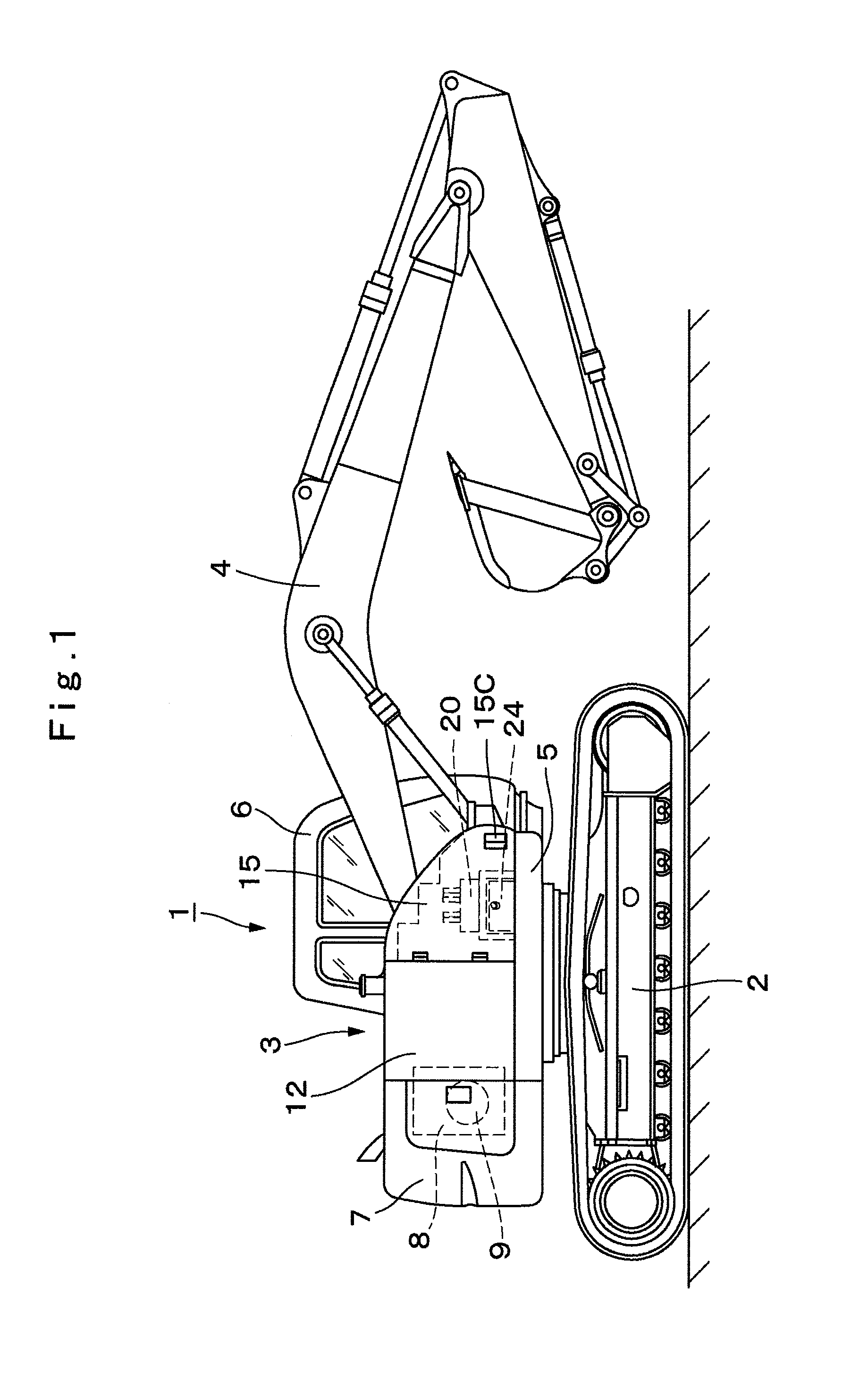
[0071]The hydraulic excavator 1 has the configuration as above and subsequently, its operation will be described.

[0072]The operator gets on the cab 6, starts the engine 8 and drives the hydraulic pump 9. The operator can advance or retreat the lower traveling structure 2 by operating a lever for running and the like. On the other hand, the operator can perform an excavating work of earth and sand and the like by moving the working mechanism 4 upward / downward by operating a lever for working.

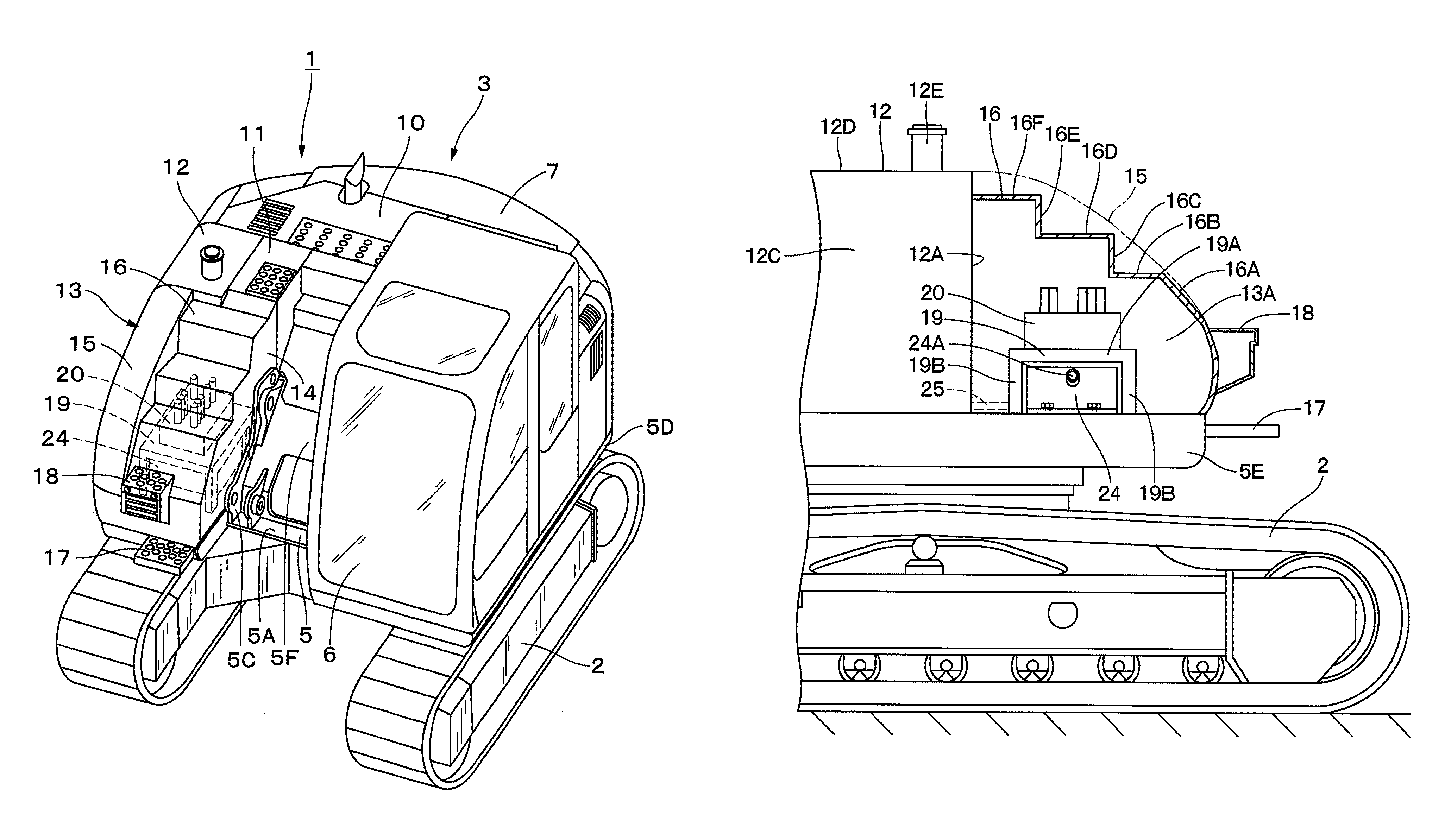
[0073]Here, during operation of the engine 8, nitrogen oxides (NOx) which is a hazardous substance is discharged from its exhaust pipe 8A. At this time, the urea water in the urea water tank 24 is supplied to the urea water injection valve 23F of the NOx purifying device 23 from the urea water supply line 25 by using the supply pump 26. The NOx purifying device 23 generates ammonia by injecting the urea water into the exhaust gas from the urea water injection valve 23F. The urea selective reduct...

second embodiment

[0079]Designated at 31 is a tank support member used in the second embodiment, and the tank support member 31 extends substantially horizontally from the front surface 11A of the operating oil tank 11 and the front surface 12A of the fuel tank 12 toward the lower step plate 16B of the upper closing plate 16. This tank support member 31 is formed having an L-shape made of a mounting portion 31A extending in the vertical direction and a support portion 31B extending in the horizontal direction. The tank support member 31 has its mounting portion 31A fixed by a bolt to a thick flat plate-shaped mounting plate 32 provided on the front surface 11A of the operating oil tank 11 and the front surface 12A of the fuel tank 12. As a result, the support portion 31B of the tank support member 31 extends to the lower side of the intermediate step plate 16D constituting the upper closing plate 16, and a space in which a urea water tank 33 which will be described later is to be arranged is formed b...

third embodiment

[0091]In the third embodiment, the urea water tank 43 is arranged within a range of the pin moving trajectory O-O which is the moving direction of the connecting pin 47, and the urea water tank 43 is configured to be detachably mounted on the support portion 41B of the tank support member 41 by using the fixing member 45.

[0092]Therefore, as illustrated in FIG. 9, when an inserting / removing work of the connecting pin 47 with respect to the left vertical plate 5B and the right vertical plate 5C of the revolving frame 5 and the working mechanism 4 is performed, a space for inserting / removing the connecting pin 47 can be ensured by removing the fixing member 45 from the mounting plate 42 and removing the urea water tank 43 from the range of the pin moving trajectory O-O which is the moving direction of the connecting pin 47, and the inserting / removing work can be performed smoothly.

[0093]As described above, in the third embodiment, the urea water tank 43 is configured to be detachably a...


PUM


Abstract

On the right front side of a revolving frame (5) constituting an upper revolving structure (3), an operating oil tank (11) and a fuel tank (12) are arranged. On the front side of this operating oil tank (11) and the fuel tank (12), an equipment accommodating case (13) forming an accommodating space (13A) inside is provided. In the accommodating space (13A) in the equipment accommodating case (13), a control valve unit (20) for controlling supply / discharge of the operating oil and a urea water tank (24) storing urea water for removing nitrogen oxides contained in an exhaust gas of the engine (8) are arranged together.

Description

TECHNICAL FIELD[0001]The present invention relates to a construction machine such as a hydraulic excavator, a hydraulic crane and the like and particularly to a construction machine on which a urea selective reduction catalyst and a urea water tank for removing nitrogen oxides contained in an exhaust gas are mounted.BACKGROUND ART[0002]In general, a hydraulic excavator which is a typical example of a construction machine is composed of an automotive lower traveling structure, an upper revolving structure rotatably mounted on the lower traveling structure, and a working mechanism capable of moving upward / downward on the front side of the upper revolving structure.[0003]The upper revolving structure is composed of a revolving frame forming a support structural member, an engine mounted on the rear side of the revolving frame, and a cab provided on the left front side of the revolving frame so as to follow the left side of the working mechanism. In the cab, an operator's seat on which ...

Claims


Application Information

Patent Timeline
Patent Type & Authority Patents(United States)
IPC IPC(8): B60K13/04E02F3/30E02F9/08
CPCE02F9/0875E02F9/0883E02F3/30E02F9/0858B60K13/04E02F9/0833E02F9/0866E02F9/0891B60Y2200/412F01N2590/08F01N2610/1406E02F9/00
Inventor KOBAYASHI, TAKAHIRONAKAMURA, TSUYOSHISATO, KENSUKEAZUMA, HIROYUKI
Owner NIHON KENKI CO LTD
Why Eureka
Try Eureka