Free-form surface gear

a surface gear and free-form technology, applied in the field of transmission gears, can solve the problems of reducing the life of the transmission gear, requiring a complex cutting tool, and a long time for cutting each tooth, so as to increase the fatigue strength and increase the fatigue strength

Active Publication Date: 2015-07-28
O OKA CORP
View PDF18 Cites 8 Cited by
  • Summary
  • Abstract
  • Description
  • Claims
  • Application Information

AI Technical Summary

Benefits of technology

[0010]The present disclosure relates to transmission gears for use in automobiles, construction machines, industrial machines, etc., and to a tooth profile of a spur gear or a helical gear. In the case of a spur gear, a tooth surface thereof is formed of a single surface selected from a cycloid surface, a trochoid surface, an epitrochoid surface, a peritrochoid surface, a circular surface, and a limacon surface or a compound surface that is a combination of surfaces selected from the above-mentioned surfaces and an involute surface. In the case of a helical gear, a tooth surface thereof is formed of a single surface selected from a cycloid helicoid surface, a trochoid helicoid surface, a circular helicoid surface, a limacon helicoid surface, a three-dimensional coordinate surface, an epitrochoid helicoid surface, and a peritrochoid helicoid surface or a compound surface that is a combination of surfaces selected from the above-mentioned surfaces and an involute helicoid surface. A bottom land, which is a surface below TIF (described below) of the tooth surface, includes a single surface selected from a cycloid surface, a trochoid surface, an epitrochoid surface, a peritrochoid surface, a circular helicoids surface, and a limacon surface. The single or compound surfaces that form the tooth surface or the bottom land are generically referred to as “free-form surfaces” in the following description. The present disclosure relates to a transmission gear having a free-form surface formed by hot forging or cold forging such that the smallest radius of curvature of a tooth surface in an area around a mating pitch point is maximized from a geometric aspect of the free form surface of the tooth surface to increase fatigue strength against bearing pressure and such that the smallest radius of curvature in an area around a tooth root is maximized from a geometric aspect of the free form surface of the tooth bottom land to increase fatigue strength against bending.
[0011]The present disclosure has been made in view of the above-described problems, and the inventors have arrived at the idea of manufacturing a forging die having a free-form surface by using the latest NC processing technology. An object of the present disclosure is to provide a transmission gear which has a tooth surface formed of a free-form surface instead of an involute surface and a root area formed of a free-form surface instead of a trochoid surface by a forging process, which is highly productive, using a forging die. With such a transmission gear, the fatigue strength against contact pressure can be increased by reducing the Hertzian stress in the area around the meshing point of the tooth surface, and the fatigue strength against bending can be increased by reducing the bending stress at a tooth root portion of the bottom land. In addition, the gear noise can be reduced.
[0013]The tooth surface of the gear is formed of a single or compound free-form surface, so that the fatigue strength against contact pressure is increased by reducing the Hertzian stress at the tooth surface and the fatigue strength against bending is increased by reducing the stress concentration at the bottom land. In addition, since the tooth surface is formed of a single or compound free-form surface, the noise can be reduced and the smallest radius of curvature of the tooth surface in the area around the mating pitch point can be maximized from a geometric aspect of the free form surface of the tooth surface. As a result, pitting or flaking at the tooth surface can be reduced. In other words, the smallest radius of curvature of the tooth surface and the smallest radius of curvature of the bottom land can be maximized by appropriately selecting a free-form surface or combining free-form surfaces. As a result, the fatigue strength against contact pressure of the tooth surface and the fatigue strength against bending of the bottom land can be increased. With regard to productivity, hot forging and cold forging, which are performed to form the gear, are highly productive and suitable for mass production.

Problems solved by technology

The contact pressure is at a maximum when the gears mesh with each other at the mating pitch points P, which leads to problems of flaking, such as pitting, and reduces the life of the gears.
However, although such a cycloid gear had a small rotational angle error and was suitable for use in clocks, a cutting tool having a complex shape was required since the gear included complex surfaces.
In addition, it took a long time to cut each tooth.
As time went by and demand for mass production of power transmission gears grew with the industrial revolution, cycloid gears, which were not suitable for mass production, disappeared.
The tool used in this method is a simple, linear rack cutter, and therefore the tooth surface is limited to being an involute surface and the bottom land is limited to being a trochoid surface; it is not possible to form other types of surfaces.
Therefore, rotational angle errors occur during the rotational motion including sliding and noise is easily generated as a result of sliding between the involute surfaces.
In addition, since the tooth surface is formed of an involute surface, Hertzian stress cannot be minimized at an area around the meshing point.
Further, in the involute gears formed by the gear generating method using linear cutting edges, the bottom land is limited to being the trochoid surface.
Therefore, there is a geometric limit to how much the radius of curvature in the area around the tooth root can be increased.
Therefore, owing to stress concentration that occurs at the tooth root portion, it is difficult to satisfy the demand for reduction in size and weight of transmissions with the gears formed by the gear generating method using linear cutting edges.
On the other hand, even with the recent progress in the numerical control (NC) processing technology, it has been difficult to manufacture a gear cutting tool for forming surfaces other than the involute surface or the trochoid surface.
That is, with regard to the tooth surfaces of the involute gears, since the involute gears that mesh with each other rotate while the involute surfaces slide along each other, rotational angle errors occur.
In addition, since the involute surfaces slide along each other, noise is easily generated and the involute surfaces are easily worn away.
In addition, since the tooth surfaces are formed of the involute surfaces, the radius of curvature cannot be increased and the Hertzian stress is maximized in the area around the meshing point.
Therefore, the fatigue strength against contact pressure is low.
Therefore, stress concentration occurs at the tooth root portion and the fatigue strength against bending is low.
For the above-described two reasons, it has been difficult to satisfy the demand for reduction in size and weight of transmissions with the involute gears formed by the gear generating method using linear cutting edges.
In addition, it has also been difficult to reduce the gear noise.

Method used


Image

  • Free-form surface gear
  • Free-form surface gear
  • Free-form surface gear

Examples


first embodiment

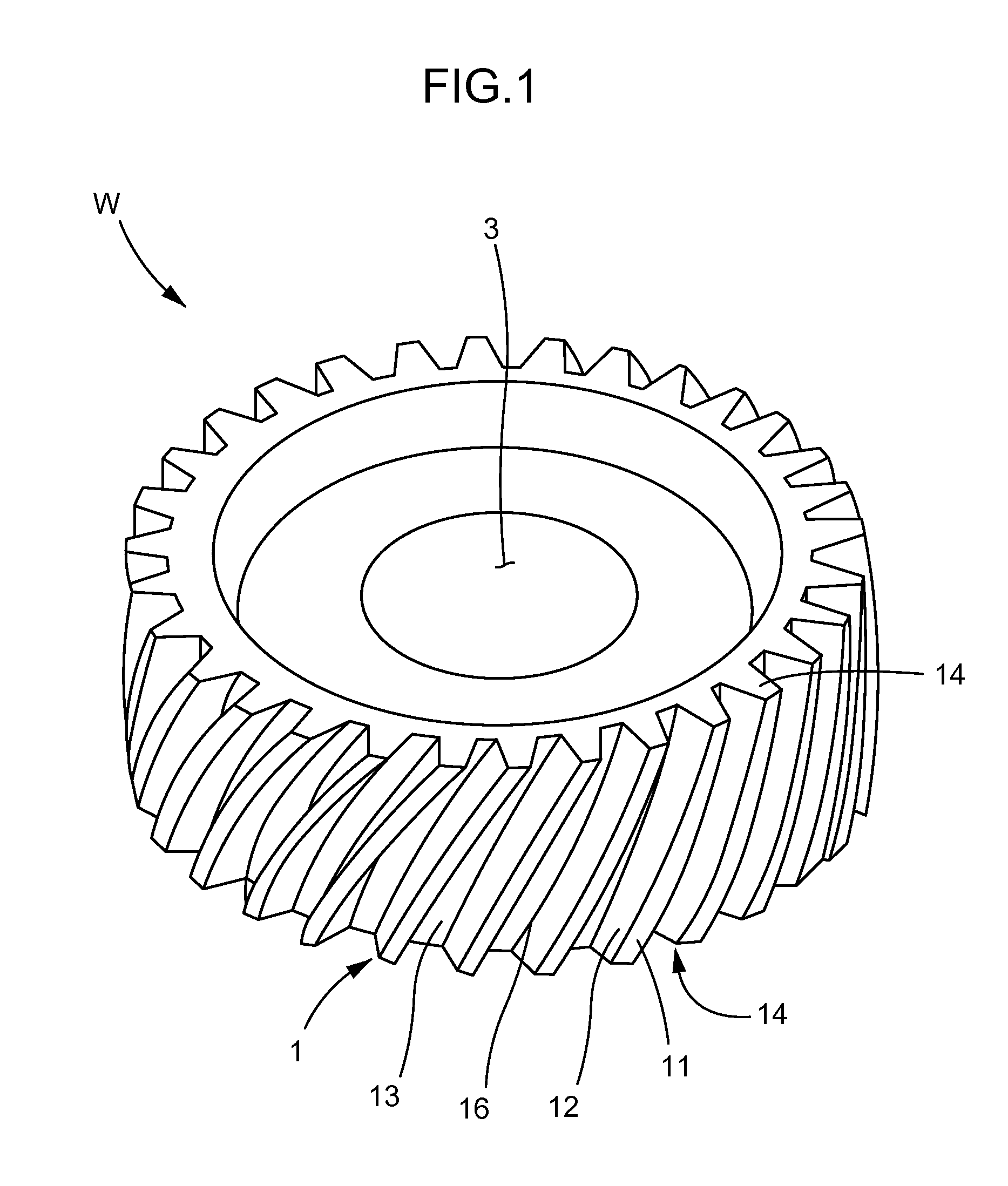
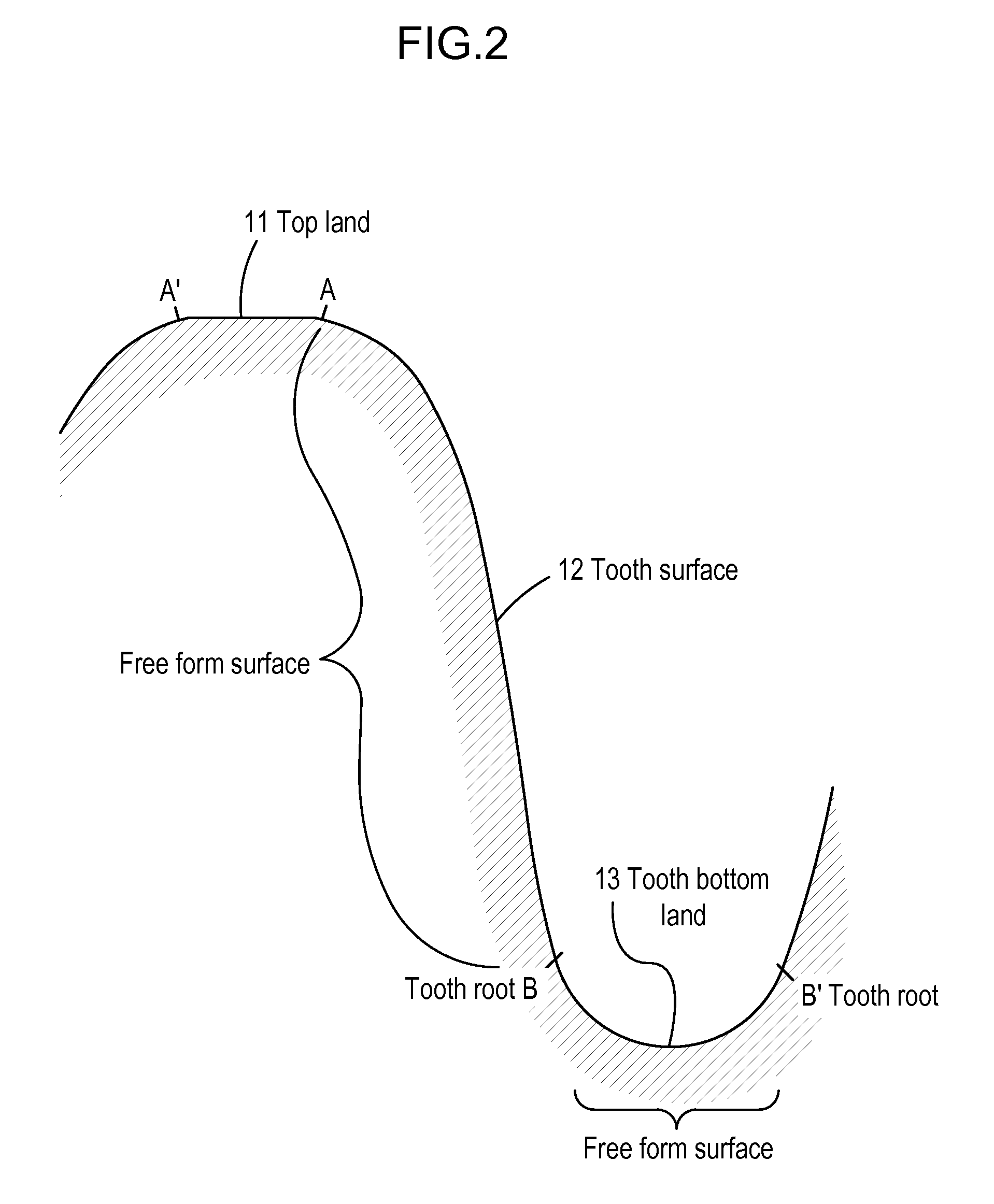
[0033]The present embodiment is applied to a spur gear or a helical gear. The present embodiment will be described with reference to FIGS. 1 and 2. FIG. 1 is a perspective view of a transmission gear according to the present embodiment. FIG. 2 is a sectional view of a tooth profile formed of a single free-form surface.

[0034]The name of each part of the transmission gear according to the present embodiment illustrated in FIG. 1 will now be described. Each of helical teeth 1 at the outer periphery of the transmission gear W includes a top land 11 that extends in a tooth trace direction, tooth surfaces 12 at the left and right sides of the top land 11, bottom lands 13 on which the tooth surfaces 12 stand, tooth end faces 14 and 14 at the top and bottom ends in the tooth trace direction, and a tooth root 16. Here, the tooth profile of the helical teeth 1, whose tooth trace direction is helical with respect to a rotational axis direction of the gear, will be described.

[0035]FIG. 2 is a n...

second embodiment

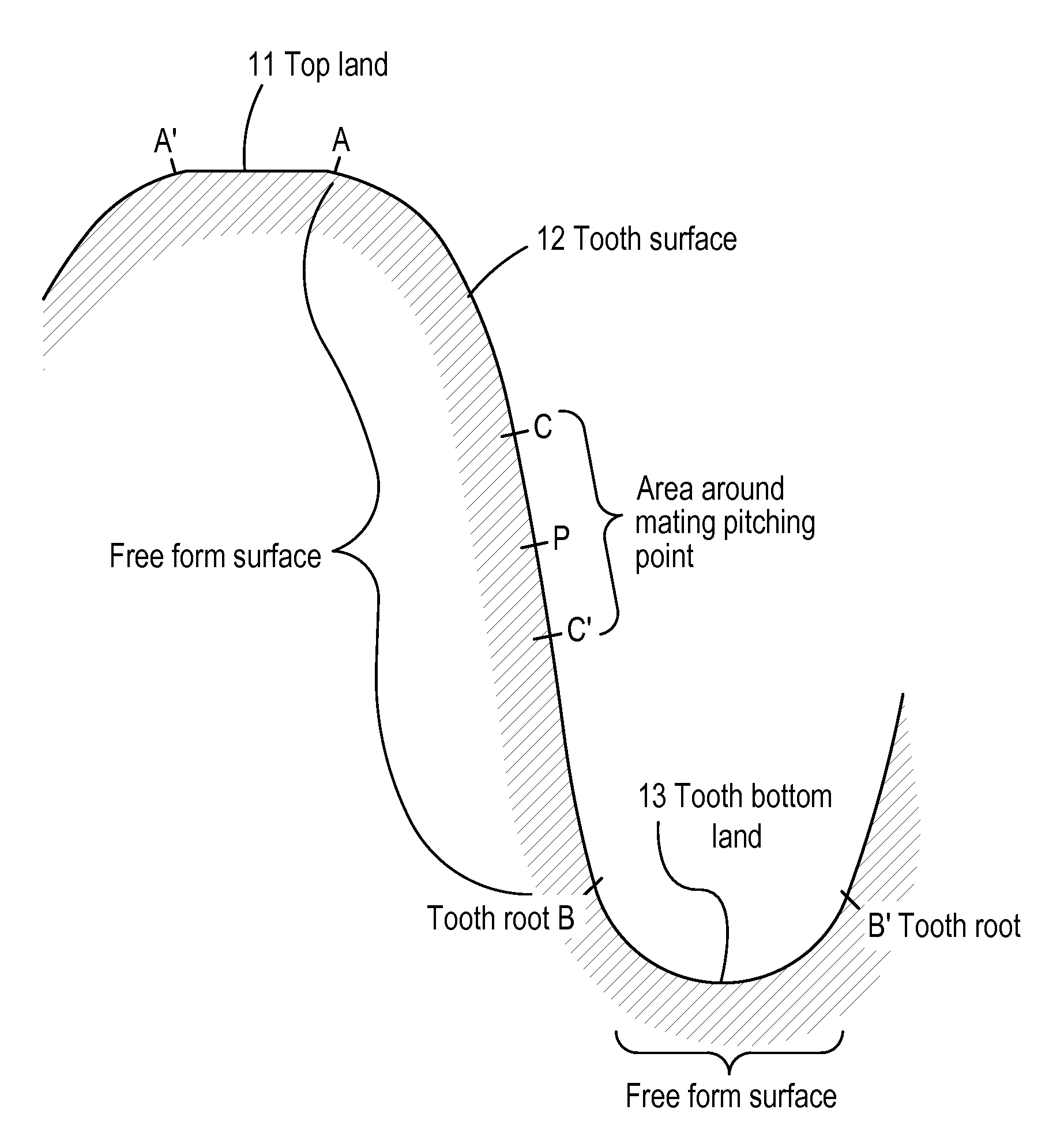
[0037]The present embodiment is applied to a spur gear or a helical gear. Here, a spur gear will be described with reference to FIG. 3. The present embodiment differs from the first embodiment in that the tooth surface is formed of a compound free-form surface. The difference from the first embodiment will be mainly described below. A sectional view along a plane perpendicular to the axis that differs from FIG. 2 is shown in FIG. 3. The tooth surface is formed of a compound free-form surface, and the bottom land is formed of a single free-form surface. The overall tooth profile is formed of a compound free-form surface 3. In the free-form surface 3 of the tooth profile, the tooth surface is formed of a compound surface of three types of surfaces, which are an epitrochoid surface in the area between symbols A and C, a cycloid surface in the area between symbols C and C′, and a trochoid surface in the area between symbols C′ and B. The bottom land in the area between symbols B and B′ ...

third embodiment

[0041]The present embodiment is applied to a helical gear. The helical gear includes a helicoid surface having a helix angle obtained by subjecting a tooth surface to a bias modification. The present embodiment will be described with reference to FIGS. 4 and 5. The present embodiment differs from the first and second embodiments in that the tooth surface is subjected to the bias modification. FIG. 4 is a perspective view of a tooth profile having a free-form surface obtained by subjecting the tooth surface to a bias-in modification. FIG. 5 is a perspective view of a tooth profile having a free-form surface obtained by subjecting the tooth surfaces to a bias-out modification.

[0042]Before describing the tooth profile, gear terms will be explained. There are two types of methods, which are the bias-in modification and the bias-out modification, for twisting the tooth surface. In the bias-in modification, the tooth surface of the gear is twisted such that the tooth surface is lowered at...


PUM

PropertyMeasurementUnit
thicknessaaaaaaaaaa
radius of curvaturesaaaaaaaaaa
radius of curvatureaaaaaaaaaa

Abstract

A transmission gear has a tooth surface formed of a free-form surface instead of an involute surface and a root area formed of a free-form surface instead of a trochoid surface. With such a transmission gear, the fatigue strength against contact pressure can be increased by reducing the Hertzian stress in the area around the meshing point of the tooth surface. The tooth surface is formed of a free-form surface in which the smallest radius of curvature in an area around a mating pitch point is maximized, and the fatigue strength against bending can be increased by reducing the bending stress at a tooth root portion of the bottom land. In addition, the gear noise can be reduced. The bottom land is formed of a free-form surface in which the smallest radius of curvature in an area around a tooth root is maximized.

Description

CROSS-REFERENCE TO RELATED APPLICATION[0001]This application is a Continuation-in-Part of PCT Application PCT / JP2010 / 007540 filed on Dec. 27, 2010, which claims priority to Japanese Application No. 2010-140565 filed on Jun. 21, 2010.FIELD OF THE APPLICATION[0002]The present disclosure relates to transmission gears for use in automobiles, construction machines, industrial machines, etc., and to a tooth profile of a spur gear or a helical gear.BACKGROUND[0003]The following description sets forth the inventor's knowledge of related art and problems therein and should not be construed as an admission of knowledge in the prior art.[0004]The gear terms used above will be described with reference to FIG. 12. FIG. 12 is an enlarged perspective view of a tooth profile. The name of each part of the tooth profile is defined as follows. That is, a helical tooth 1 includes a top land 11 (area between symbols A and A′), tooth surfaces 12 (area between symbols A and B) at the left and right sides ...

Claims


Application Information

Patent Timeline
Patent Type & Authority Patents(United States)
IPC IPC(8): F16H55/08F16H55/02B21J5/02F16H55/17F16H55/00F16H55/10B21K1/30
CPCF16H55/02B21J5/025B21K1/30B21K1/305F16H55/08F16H55/0886F16H55/17F16H2055/0893Y10T29/49469Y10T74/19953Y10T74/19972
Inventor O-OKA, MITSUSHIGEKAWASAKI, YOSHIKISHIMOMURA, MITSUHIKO
Owner O OKA CORP
Why Eureka
Try Eureka