Metallic separator for fuel cells and method of manufacturing the metallic separator

a fuel cell and separator technology, applied in the direction of sustainable manufacturing/processing, final product manufacturing, electrochemical generators, etc., can solve the problems of difficult evaluation of local corrosion, difficult maintenance of corrosion resistance metallic separators, and long time-consuming maintenance of corrosion resistance, etc., to reduce the susceptibility to stress-corrosion cracking, improve corrosion resistance, and reduce the effect of stress-corrosion cracking

Active Publication Date: 2015-08-04
UNIVERSITY OF YAMANASHI
View PDF28 Cites 1 Cited by
  • Summary
  • Abstract
  • Description
  • Claims
  • Application Information

AI Technical Summary

Benefits of technology

[0086]According to the thirty-first and thirty-second aspects, a more uniform and tighter coating layer can be formed in comparison with the case of forming a channel by directly stamping a metal plate and thereafter forming a coating layer thereon. In this way, the occurrence of stress-corrosion cracking which can be easily caused in a bending portion by stamping or the like can be reduced.
[0087]According to the present invention, as described above, a metallic separator for fuel cells having reduced susceptibility to stress-corrosion cracking and excellent corrosion resistance can be obtained to enable maintenance of the desired reaction efficiency.

Problems solved by technology

However, the maintenance of the corrosion resistance during a long time has not been attained by any of the conventional methods.
Thus, the corrosion resistance metallic separators have been a serious challenge over a long time.
However, while it is possible to evaluate entire-surface corrosion, it is difficult to evaluate local corrosion such as local pitting, grain boundary corrosion or stress-corrosion cracking.
In particular, it is difficult to find a sign of stress-corrosion cracking.
In many cases, stress-corrosion cracking is found in a time period of several to five years after a start of use.
There has been a difficulty in devising measures against it.
For example, in the case of stainless steel, corrosion occurs when the material is exposed to water containing a halogen or oxygen as a corrosion condition.
In some cases, pitting is a starting point of stress-corrosion cracking.
In a case where a carbide of chromium is precipitated at a grain boundary in a metallic material to form a chromium-deficient layer in the vicinity of the crystal grain boundary, grain boundary corrosion may occur and progress to cause stress-corrosion cracking.
Further, the interior of a fuel cell is in a corrosive environment in which a halogen generated, for example, in a polymer coating or by decomposition of an electrolyte membrane, oxygen and water coexist.
With metallic separators, therefore, there is a serious problem that stress-corrosion cracking occurs easily.
However, electric conductivity and corrosion resistance are in a trade-off relationship and designing a coating material and improving film making techniques are one of the important challenges to be achieved.
These materials in the metallic separator become a cause of corrosion of the metallic separator and also become a cause of reduction in reaction efficiency.
Thus, selection of a method of forming a channel for reactant gas and a metallic material has been an important challenge influencing the reactant gas flow distribution and the reaction efficiency (power generation efficiency).

Method used


Image

  • Metallic separator for fuel cells and method of manufacturing the metallic separator
  • Metallic separator for fuel cells and method of manufacturing the metallic separator
  • Metallic separator for fuel cells and method of manufacturing the metallic separator

Examples


first embodiment

(First Embodiment)

[0136]The present embodiment is an example of a metallic separator in which a channel is formed by using a channel-forming member without pressing a metal plate.

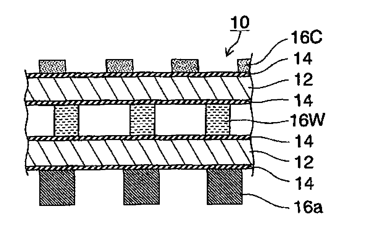
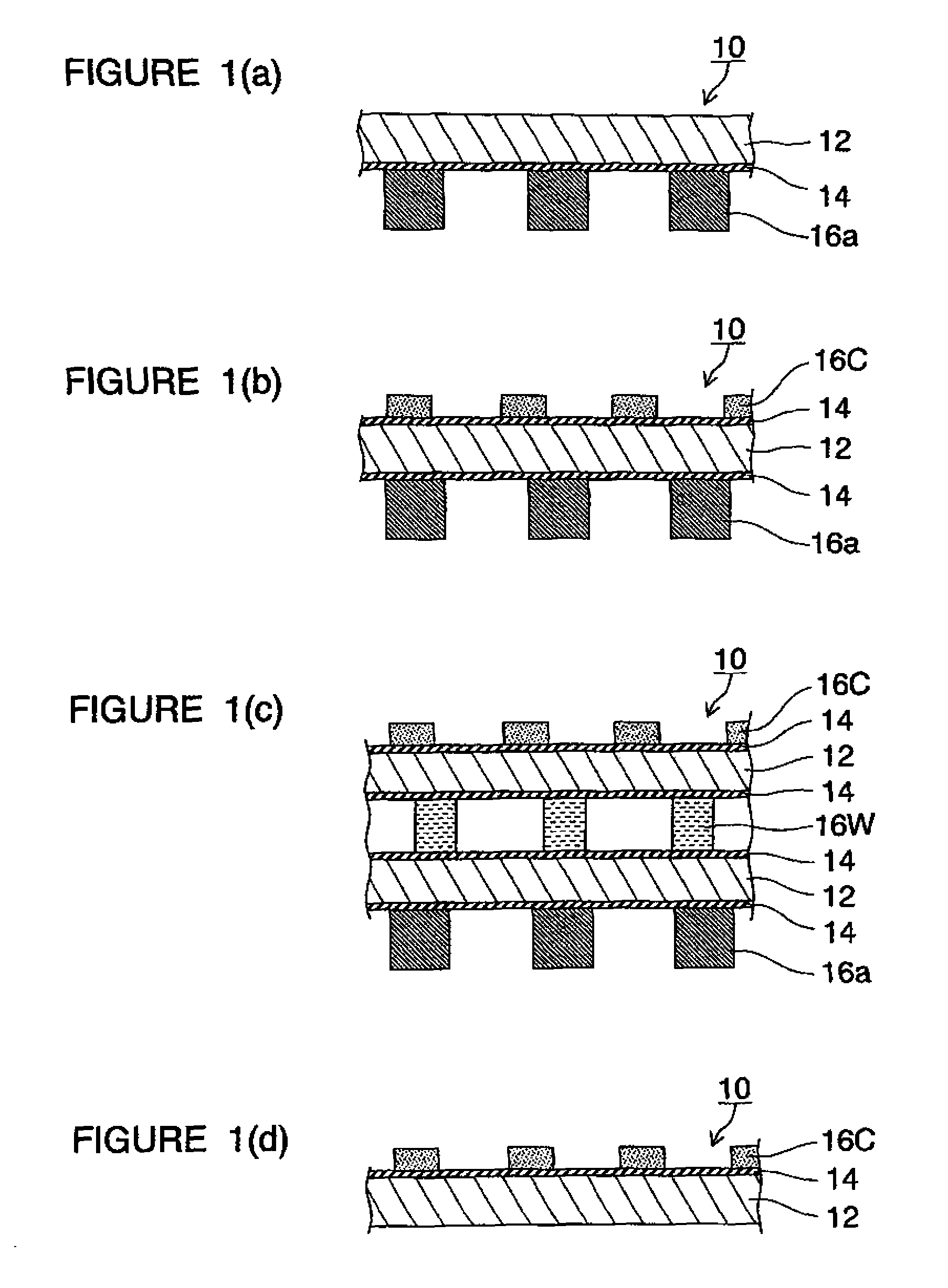
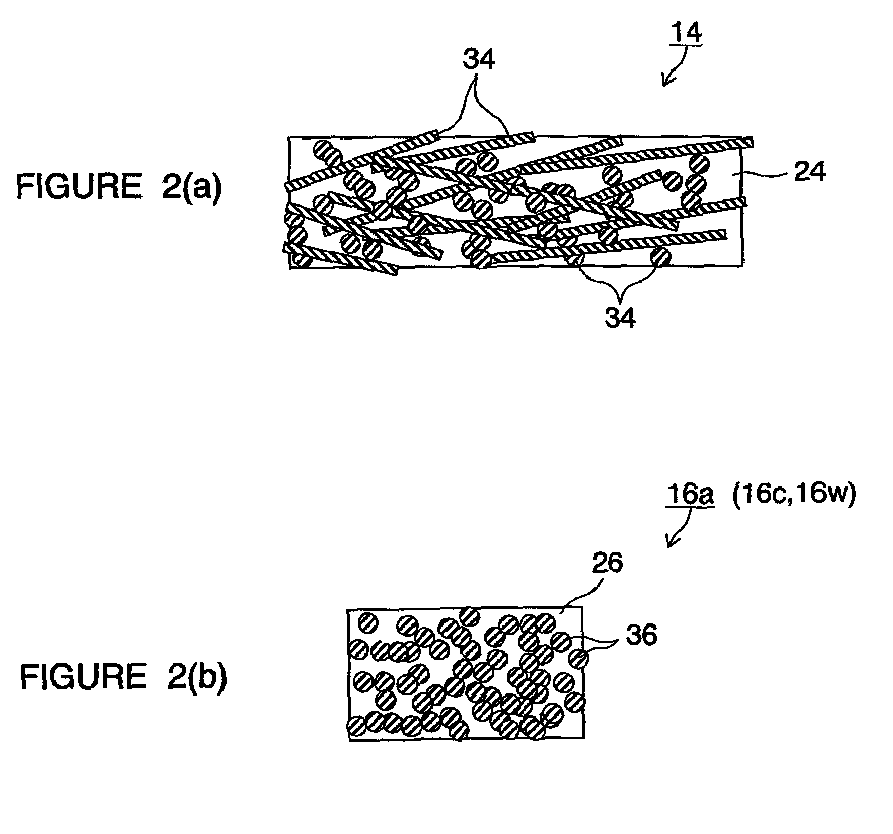
[0137]The construction of the metallic separator in the present embodiment will first be outlined. FIG. 1 are schematic sectional views of metallic separators 10 for fuel cells in several patterns. In FIG. 1, FIGS. 1(a) and 1(d) are partial sectional views of metallic separators 10 used in opposite end portions of a stacked-cell battery. FIGS. 1(b) and 1(c) are partial sectional views of metallic separators 10 used in inner portions of the stacked-cell battery. In these figures, FIG. 1(c) is a partial sectional view of a metallic separator 10 having a cooling structure. FIG. 2 are partial schematic views for explaining members constituting FIG. 1. In the figures, the same reference characters denote the same objects or the same functions.

[0138]The metallic separator 10 in FIG. 1(a) or 1(d) showing a basic c...

second embodiment

(Second Embodiment)

[0195]The present embodiment is an example of a metallic separator having a channel formed by first forming a coating layer on a surface of a metal plate and thereafter forming the plate molding.

[0196]FIG. 6 are partial sectional views of a metallic separator 10′ for fuel cells in the present embodiment. In FIG. 6, FIG. 6(a) shows a case where a bent portion in a channel section is rounded and FIG. 6(b) shows a case where a bent portion in a channel section is not rounded. FIG. 7 are schematic diagrams for explaining an example of manufacture of the metallic separator 10′ in the present embodiment. In the diagrams, the same reference characters as those in FIGS. 1 to 5 for the first embodiment denote the same objects or functions. The same descriptions of the same objects or functions as those for the first embodiment will not be repeated.

[0197]The metallic separator 10′ in the present embodiment is formed in the same manner as the metallic separator in the first ...

examples

[0211]Examples of the present invention will be described below. The present invention is not limited to the examples described below. A power generation test of a polymer-electrolyte fuel cell using the metallic separator 10 in the first embodiment of the present invention was performed.

[0212]The construction of the polymer electrolyte fuel cell 100 will first be described. FIG. 8 is a perspective view showing the unit-cell construction of a polymer electrolyte fuel cell 100. This fuel cell 100 has a structure in which a pair of metallic separators 50 of the present invention are placed above and below an MEA (membrane electrode assembly) 40 so that the MEA is in contact with and tightly pinched between the metallic separators 50. The metallic separator 50 has an anode-side channel formation face 50A formed in its upper face and has a cathode-side channel formation face 50C formed in its lower face. The structure of the cathode-side channel formation face 50C is substantially the s...


PUM

PropertyMeasurementUnit
thicknessaaaaaaaaaa
porosityaaaaaaaaaa
porosityaaaaaaaaaa

Abstract

A metallic separator for fuel cells having a metal plate, an electroconductive coating layer covering at least a surface in front and back surfaces of the metal plate which contacts a raw material and/or a reaction product, and an electroconductive channel-forming member disposed on a surface of the coating layer and forming a channel for the raw material and/or the reaction product and/or a channel for a cooling medium for cooling. A surface layer on the metal plate has a tensile residual stress within such a range that no stress-corrosion cracking occurs.

Description

TECHNICAL FIELD[0001]The present invention relates to a metallic separator for fuel cells and a method of manufacturing the metallic separator and, more particularly, to a metallic separator suitable for stacked fuel cells using a polymer electrolyte membrane, a method of manufacturing the metallic separator, and a fuel cell. The present application is accompanied with claim of priority under the Paris convention based on Japanese Patent Application No. 2005-178036 based on the Japanese Patent Law.BACKGROUND ART[0002]A polymer electrolyte fuel cell (PEFC) is a device for obtaining electric energy by causing a hydrogen gas provided as a fuel and oxygen provided as an oxidizer to react with each other. A unit cell formed as this fuel cell is constituted by a membrane electrode assembly (MEA) which is formed of a pair of porous electrodes (porous supporting layer+catalyst layer) are opposed to each other with a polymer electrolyte membrane interposed therebetween, and which is sandwich...

Claims


Application Information

Patent Timeline
Patent Type & Authority Patents(United States)
IPC IPC(8): H01M8/02
CPCH01M8/0206H01M8/021H01M8/0228H01M8/0234H01M8/0239H01M8/0243H01M8/0254H01M8/0267Y02E60/50H01M8/0258Y02P70/50H01M8/0245H01M8/04029H01M8/1018H01M2008/1095H01M2250/20Y02T90/40
Inventor WATANABE, MASAHIROUCHIDA, HIROYUKIYAMASHITA, HISAOMIYATAKE, KENJI
Owner UNIVERSITY OF YAMANASHI
Why Eureka
Try Eureka