
Internal combustion engine reformer installation

a technology for reformers and combustion engines, applied in the direction of carburettors, fuel systems, non-fuel substance addition to fuel, etc., can solve the problems of high surface temperature, fuel coking risk, etc., and achieve the effect of increasing the energy efficiency of the overall installation and enhancing the safety of such an installation

Active Publication Date: 2015-09-22
GE JENBACHER
View PDF23 Cites 4 Cited by
  • Summary
  • Abstract
  • Description
  • Claims
  • Application Information

AI Technical Summary

Benefits of technology

The invention is a process for improving safety and controlling the coking tendency of fuel in an installation. The invention also aims to increase energy efficiency by more efficiently using available energy flows. The fuel and air are preheated separately using two heat exchangers to reduce the amount of inflammable gas in the installation, lower preheating temperatures for the fuel mixture, and prevent fuel coking. The addition of steam to the fuel gas prior to the second heat exchanger reduces the temperature of the synthesis gas and increases energy efficiency. The synthesis gas can be cooled using two series-connected cooling elements, and the waste heat from the cooling elements can be used for heating other substance flows in the internal combustion engine. The temperature of the synthesis gas should be between -30 to -40°C for optimal conditions in the feed of the synthesis gas to the internal combustion engine. The cooling arrangement is connected in series downstream of the heat exchangers to achieve high preheating temperatures for the substance flows intended for the reformer. The heating element can be a heat exchanger in heat-coupling relationship with the heat flow which is taken from the synthesis gas by the first cooling element of the synthesis gas cooling arrangement.

Problems solved by technology

What is problematical in that respect is that the preheating temperature for the flow into the reformer cannot be selected to be just as high as may be desired as that mixture is in fact burnable and consequently high surface temperatures represent a safety risk.
In addition, at excessively high temperatures, there is the risk of coking of the fuel, that is to say unwanted thermal decomposition of the hydrocarbons contained therein.

Method used


Image

  • Internal combustion engine reformer installation
  • Internal combustion engine reformer installation
  • Internal combustion engine reformer installation

Examples


Embodiment Construction

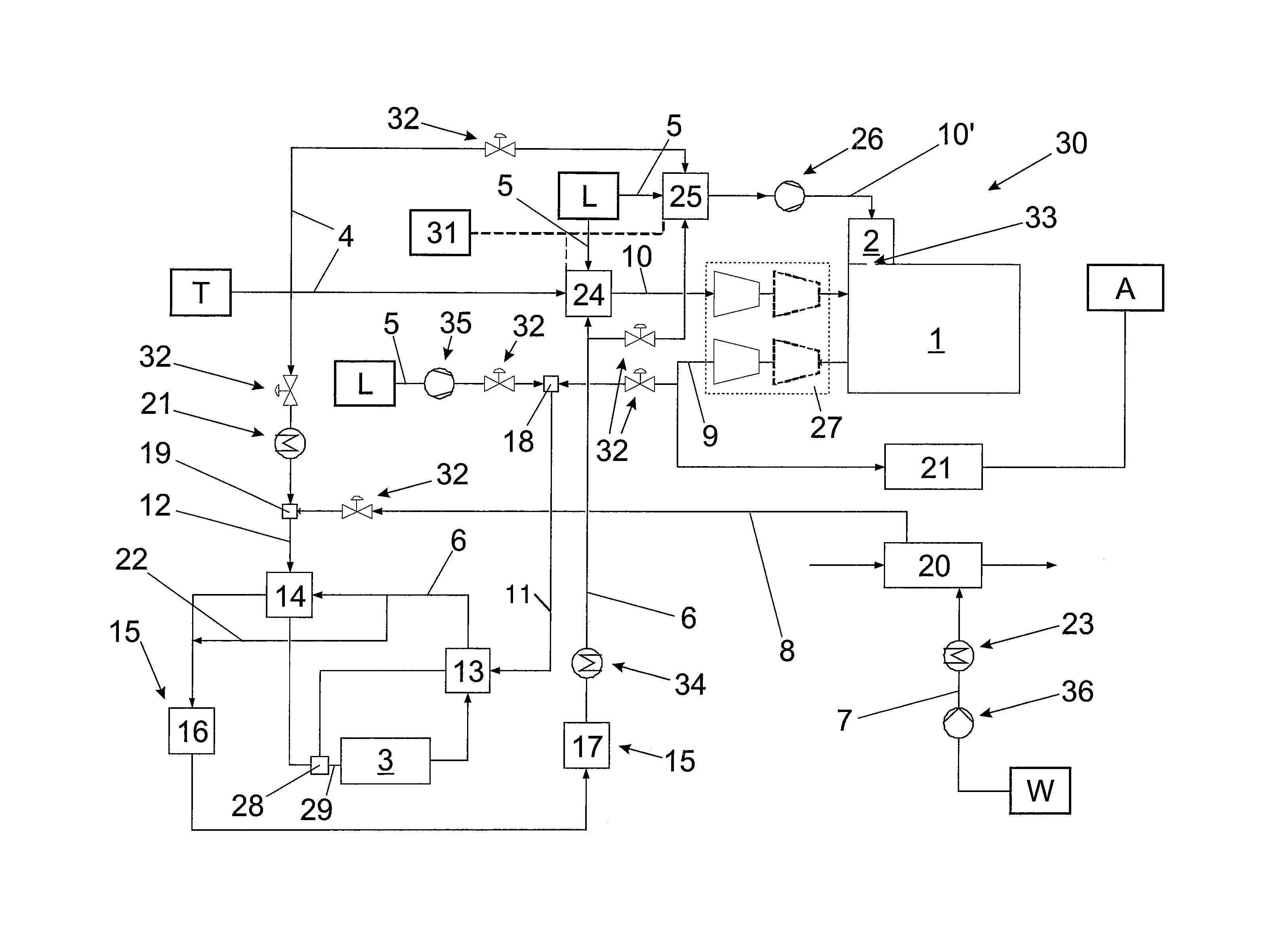
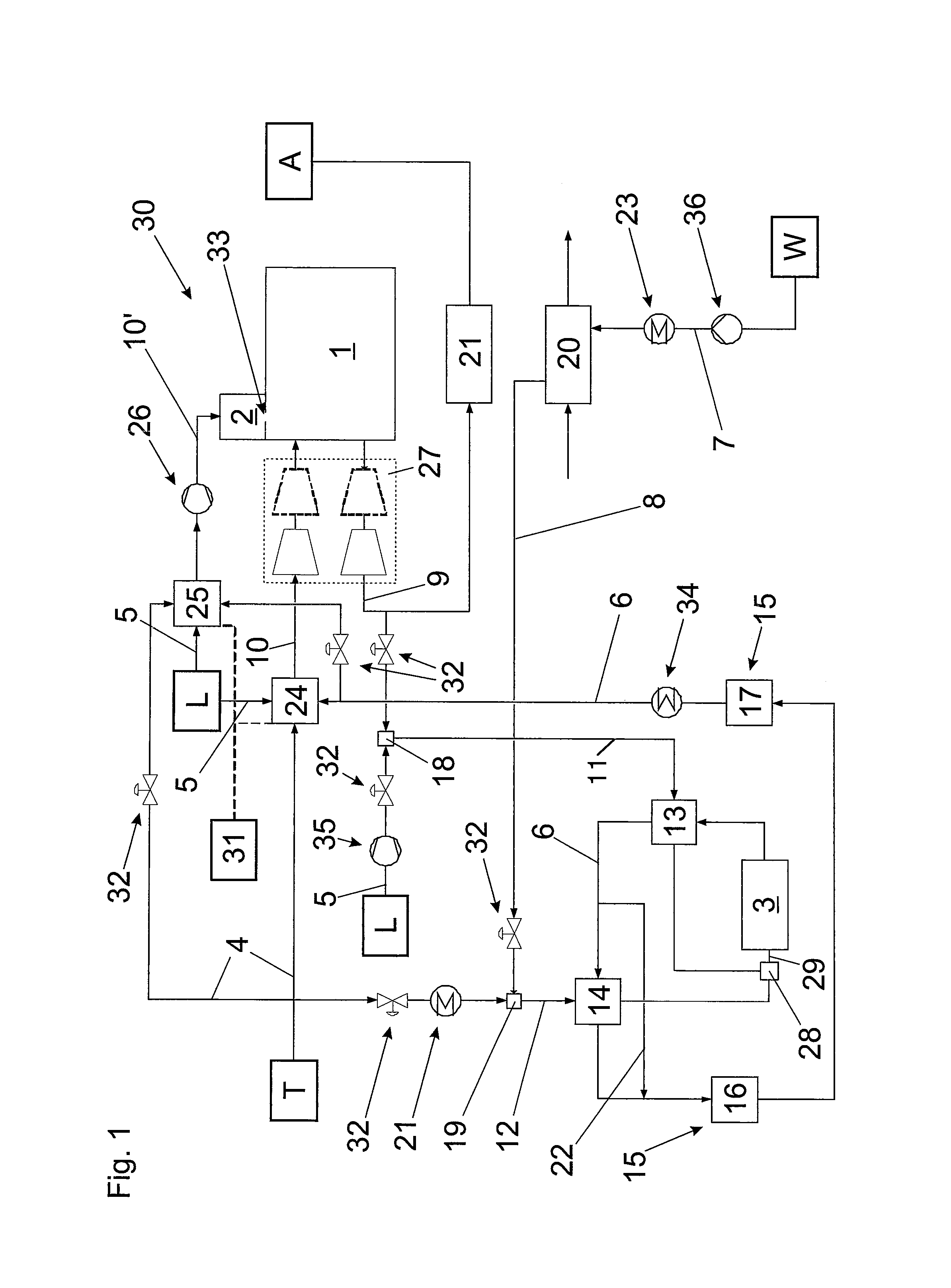
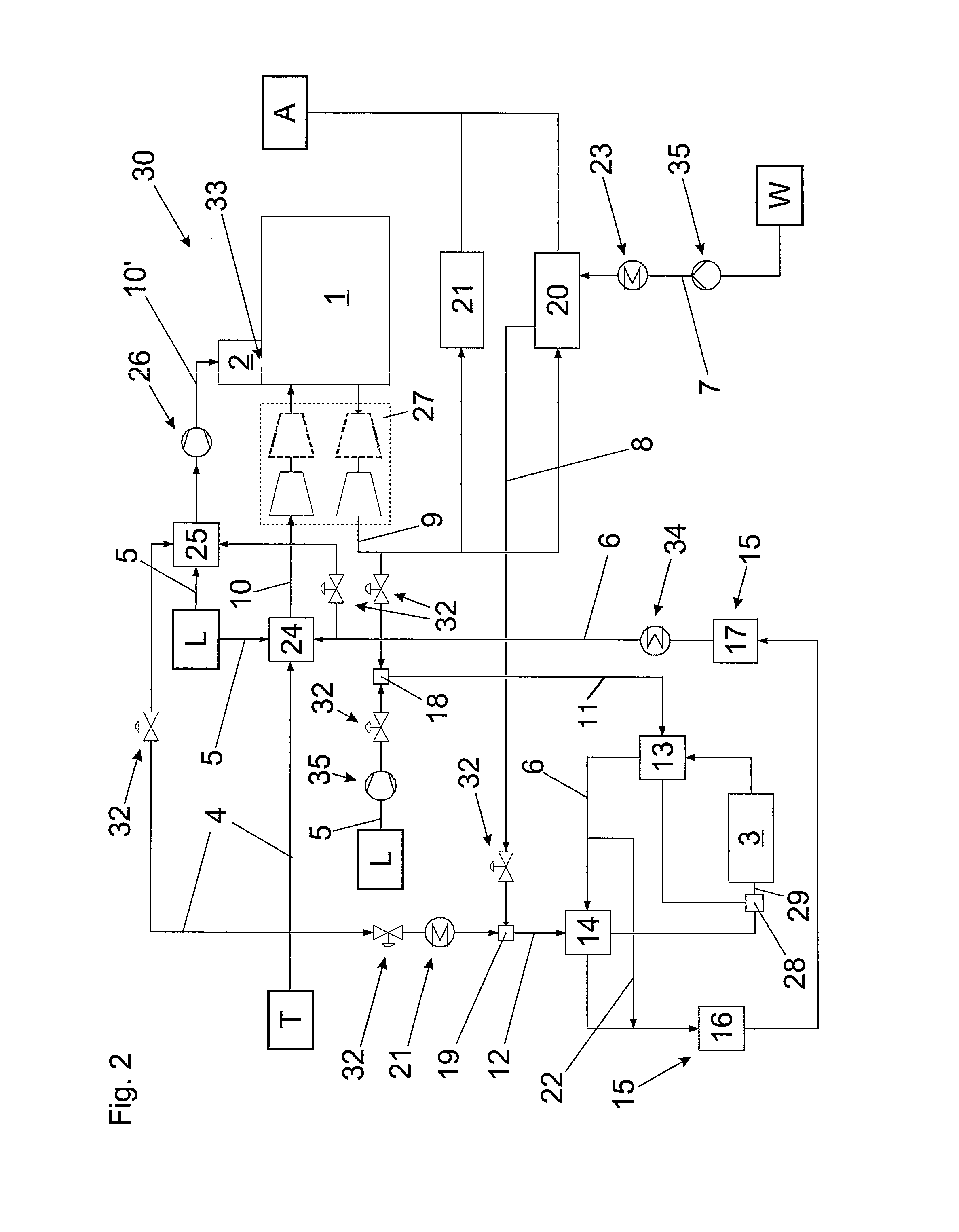
[0029]FIG. 1 shows the circuitry of an internal combustion engine reformer installation. It shows the main combustion 1, the pre-combustion chamber 2, the through-flow opening 33 and the reformer 3. Air L is fed to the internal combustion engine 30 by way of the air feed conduits 5, fuel from the fuel reservoir T is fed thereto by way of the fuel feed conduits 4 and synthesis gas is fed thereto by way of the synthesis gas feed conduit 6. The first combustion gas mixer 24 and the second combustion gas mixer 25 mix therefrom the first combustion mixture and the second combustion mixture respectively. The first combustion mixture is fed to the main combustion chamber 1 by way of the first mixture conduit 10 and the second combustion mixture is fed to the pre-combustion chamber 2 by way of the second mixture conduit 10′. In addition the internal combustion engine 30 has a compressor 26 in the second mixture conduit 10′, a turbocharger 27 and an exhaust gas conduit 9. The precise configu...


PUM


Abstract

An internal combustion engine reformer installation comprises an internal combustion engine, a mixing device having a first feed conduit for a first substance flow and a second feed conduit for a second substance flow, wherein a mixture can be produced from the first and second substance flows in the mixing device, a reformer for reforming the mixture to afford a synthesis gas, a mixture conduit connected to the mixing device and the reformer, and a synthesis gas feed conduit connected to the reformer and the internal combustion engine. A first heat exchanger in heat-coupling relationship with the first feed conduit and a second heat exchanger in heat-coupling relationship with the second feed conduit are arranged in the synthesis gas feed conduit.

Description

BACKGROUND OF THE INVENTION[0001]1. Field of the Invention[0002]The present invention concerns an internal combustion engine reformer installation having the features of a classifying portion.[0003]2. Description of Related Art[0004]Internal combustion engine reformer installations of the general kind set forth are to be found for example in U.S. Pat. No. 6,508,209 B1, JP 2001 152846 A or WO 2008 / 150370 A1. The inventions disclosed therein use the principle described hereinafter.[0005]In a reformer a synthesis gas is produced from fuel, air and possibly steam and / or a portion of the exhaust gas flow of an internal combustion engine. The synthesis gas is then fed together with air and possibly further fuel to the internal combustion engine. That affords two advantages. On the one hand gases / emissions which are unwanted in the engine exhaust gas such as for example nitrogen oxides, carbon monoxide and unburnt hydrocarbons are reduced. On the other hand the synthesis gas is hydrogen-be...

Claims


Application Information

Patent Timeline
Patent Type & Authority Patents(United States)
IPC IPC(8): F02G5/00F02M15/00F02M25/12F02B53/04F02B43/10
CPCF02B43/10F02M25/12Y02T10/121Y02T10/12
Inventor GRUBER, FRIEDRICHWALL, GUNTHERURL, MICHAEL
Owner GE JENBACHER
Learn More