Phase separated silicon-tin composite as negative electrode material for lithium-ion batteries

a lithium-ion battery, phase separated silicon technology, applied in the direction of oxide conductors, non-metal conductors, cell components, etc., can solve the problems of low capacity of such lithium insertion, fracture of active silicon materials, loss of electrical contact with conductive additives or current collectors, etc., to reduce diffusion induced stress and mitigate fracture of larger composite particles

Active Publication Date: 2015-09-22
GM GLOBAL TECH OPERATIONS LLC
View PDF3 Cites 58 Cited by
  • Summary
  • Abstract
  • Description
  • Claims
  • Application Information

AI Technical Summary

Benefits of technology

[0005]In accordance with embodiments of this invention, an improved negative electrode material is formed by combining silicon and tin as intermixed, but immiscible, solid phases. A particulate composite of silicon and tin is formed in which the silicon and tin are phase-separated. Both phases are receptive to the insertion and extraction of lithium atoms. The composite is formed with a two-phase or multi-phase structure that is nanometer to micrometer in characteristic length and is achieved by controlling the synthesis process to produce the mixed phases to be below the critical size for the generation of micro-cracks due to the repeated insertion of lithium into the mixed phases. In a preferred embodiment, confined particulate architectures are formed wherein the silicon phases are separated in a tin phase matrix. Such a microstructure provides several advantages: (1) the tin phase is electrically conductive, which enables electrons to reach the island-like silicon phase particles, (2) the diffusion of lithium in tin is much faster than in silicon, which can reduce the concentration gradient of lithium ions through the larger composite particles of silicon and tin, in effect reducing the diffusion induced stress to mitigate the fracture of the larger composite particles, (3) if a crack is generated in the composite material, the relatively soft tin matrix tends to absorb the elastic strain energy and prevent the micro-cracks from propagating, and (4) the immiscible characteristics of silicon and tin and their phase separation minimizes electrochemical sintering and thus prevents coalescence of the particles that would otherwise lead to rapid mechanical degradation of the electrode material.
[0007]In accordance with practices of the invention, the mechanical degradation that occurs when pure tin or silicon is used for lithium insertion is thus mitigated by tuning the Si / Sn ratio of the tin-silicon composite. We also demonstrate that at suitable Si / Sn ratios, phase separation occurs with amorphous phase clusters of silicon being embedded in a generally continuous phase of crystalline or amorphous tin. The resulting negative electrode materials exhibit significant improvements in charge storage capability along with excellent cycling stability.
[0008]Thus, in accordance with practices of the invention, phase separated composites of tin and silicon are formed as relatively thin layers on a suitable current collector for use as negative electrode material in the cells of a lithium ion battery. By thus using this phase separated combination of tin and silicon, the lithium-insertion capacity of each cell is increased to improve the volumetric and / or gravimetric capacity of lithium-ion batteries.

Problems solved by technology

While graphitic carbon is a durable and useful lithium-intercalating, negative electrode material for lithium-ion cells, it has a relatively low capacity for such lithium insertion.
However, the volume change of up to 300 volume percent for silicon during lithiation and delithiation processes leads to fracture of the active silicon material and / or loss of electrical contact with the conductive additives or the current collectors.
And tin has the same problem of a large volume expansion upon lithiation, leading to rapid capacity degradation.
Both problems shorten the effective cycling capacity of a battery.

Method used


Image

  • Phase separated silicon-tin composite as negative electrode material for lithium-ion batteries
  • Phase separated silicon-tin composite as negative electrode material for lithium-ion batteries
  • Phase separated silicon-tin composite as negative electrode material for lithium-ion batteries

Examples


Embodiment Construction

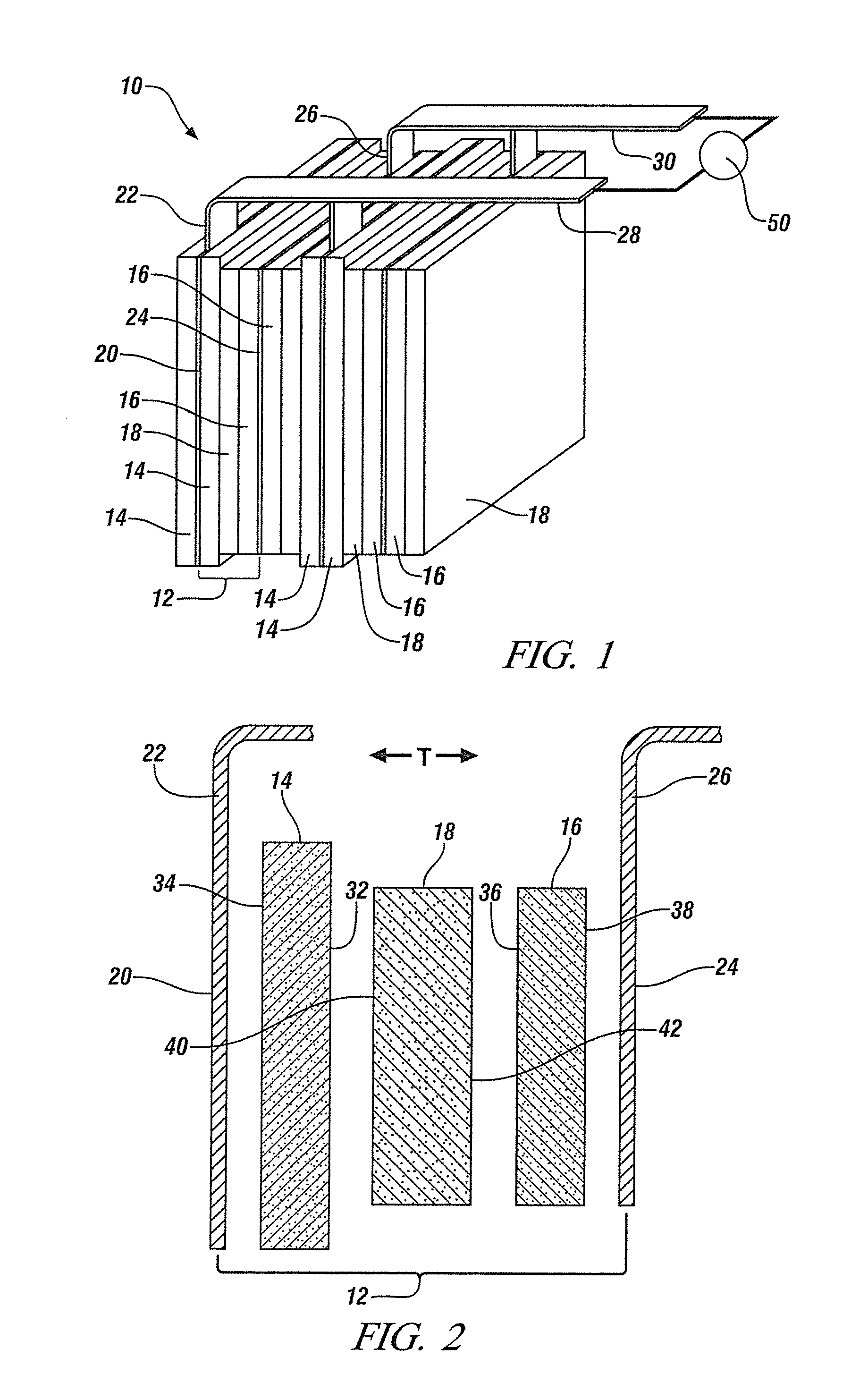
[0016]An exemplary and generalized illustration of a lithium-ion battery 10 is depicted in FIG. 1. The lithium-ion battery 10 shown here includes several thin rectangular-shaped electrochemical battery cells 12 that are each bracketed by metallic current collectors. The electrochemical battery cells 12 are stacked side-by-side in a modular configuration and, in this example, connected in parallel. A lithium-ion battery 10 may be formed of many like electrochemical cells in electrical series or in parallel connection to form a lithium ion battery that exhibits the voltage and current capacity demanded for a particular application. It should be understood the lithium ion battery 10 shown here is only a schematic illustration. FIG. 1 is presented to show the relative position and physical interactions of the various components that constitute the electrochemical battery cells 12 (i.e., the electrodes and the separator); it is not intended to inform the relative sizes of the electrochem...


PUM

PropertyMeasurementUnit
sizeaaaaaaaaaa
sizeaaaaaaaaaa
thicknessaaaaaaaaaa

Abstract

A composite of silicon and tin is prepared as a negative electrode composition with increased lithium insertion capacity and durability for use with a metal current collector in cells of a lithium-ion battery. This electrode material is formed such that the silicon is present as a distinct amorphous phase in a matrix phase of crystalline tin. While the tin phase provides electron conductivity, both phases accommodate the insertion and extraction of lithium in the operation of the cell and both phases interact in minimizing mechanical damage to the material as the cell experiences repeated charge and discharge cycles. In general, roughly equal atomic proportions of the tin and silicon are used in forming the phase separated composite electrode material.

Description

TECHNICAL FIELD[0001]This invention pertains to the preparation of negative electrode materials for lithium-ion batteries. More specifically, this invention pertains to the preparation and use of composite particles that contain nanoscale islands of amorphous silicon phases embedded in crystalline or amorphous tin phases as negative electrode material for cyclic insertion and extraction of lithium in the operation of a lithium-ion battery. The combination of suitable atomic proportions of tin and silicon, and the sizes of the respective phases in such composites enables the insertion of increased amounts of lithium over repeated electrochemical cycles with less damage to the particulate negative electrode material.BACKGROUND OF THE INVENTION[0002]Lithium-ion batteries are used as electric storage systems for powering electric and hybrid electric vehicles. These batteries comprise a plurality of suitably interconnected electrochemical cells arranged to provide a predetermined electri...

Claims


Application Information

Patent Timeline
Patent Type & Authority Patents(United States)
IPC IPC(8): H01M4/134H01M4/04H01M4/38H01M4/1395H01M10/052B82Y30/00H01B1/04H01B1/08
CPCH01M4/0426H01M4/0423H01M4/0483H01M4/134H01M4/1395H01M4/386H01M4/387H01M10/052B82Y30/00H01B1/04H01B1/08Y02E60/122Y02E60/10
Inventor XIAO, XINGCHENGSACHDEV, ANIL K.VERBRUGGE, MARK W.LIU, PINGWANG, JOHN S
Owner GM GLOBAL TECH OPERATIONS LLC
Why Eureka
Try Eureka