Non-saturating receiver design and clamping structure for high power laser based rangefinding instruments

a laser rangefinder and receiver technology, applied in the field of laser based rangefinders, can solve the problems of severe saturation problems, easy saturation of the returned signal, and complicated conventional monoblock laser receiver designs, and achieve the effect of fast recovery and fast visibility of subsequent pulses

Active Publication Date: 2015-10-06
LASER TECH INC +1
View PDF49 Cites 4 Cited by
  • Summary
  • Abstract
  • Description
  • Claims
  • Application Information

AI Technical Summary

Benefits of technology

[0007]The present invention advantageously provides a non-saturating receiver design and clamping structure for high power laser based rangefinding instruments which solves the receiver saturation issues attendant their use in conjunction with high power laser devices. The design disclosed herein utilizes relatively inexpensive, commercially available, light weight, and power efficient components without the need for complicated hybrid devices. In operation, the receiver design of the present invention provides a system which is inherently non-saturating along with a very quick recovery time on the order of just a few nanoseconds.
[0010]The receiver design of the present invention is non-saturating in operation and also provides exceptionally quick recovery from a return laser pulse as soon as the light pulse reflected from a target and detected by the photodiode has gone away. Through the use of a novel and inexpensive clamping circuit in accordance with the present invention much faster visibility of a subsequent pulse is provided following a severe overload by rapidly re-establishing the bias on the photodetector back to its operating point. At this stable operating point where there is no voltage change (dv / dt) in the circuit and, since there is no dv / dt, there is also no current flowing through the photodiode that would otherwise appear to the receiver to be a signal coming from a target.

Problems solved by technology

The difficulty with such high powered pumped laser devices is that the returned signal easily saturates the associated receiver.
For example, reflecting such a pumped laser signal off a blade of grass 10 meters away can result in a return signal of 50 milliamps which is 1,000,000 times the receiver detection threshold of 50 nanoamps causing severe saturation problems.
Currently, conventional monoblock laser receiver designs are extremely complicated, incorporating multi-stacked hybrid devices which are concomitantly expensive to design and produce.

Method used


Image

  • Non-saturating receiver design and clamping structure for high power laser based rangefinding instruments
  • Non-saturating receiver design and clamping structure for high power laser based rangefinding instruments
  • Non-saturating receiver design and clamping structure for high power laser based rangefinding instruments

Examples


Embodiment Construction

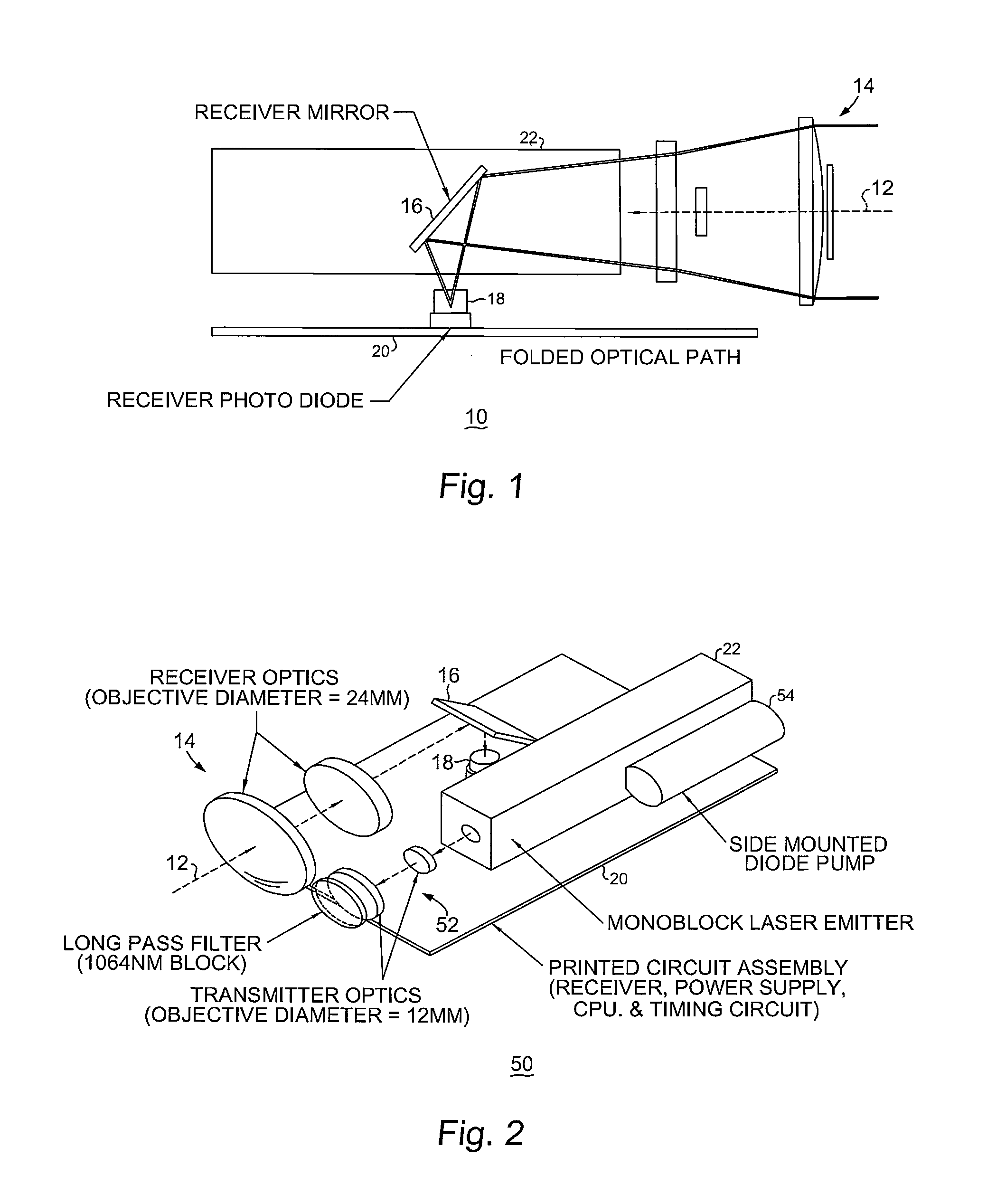
[0017]With reference now to FIG. 1, a simplified, side elevational view of the receiver 10 portion of a rangefinding device in accordance with an embodiment of the present invention is shown. The receiver 10 receives laser signals which have been reflected by a target as emitted by an associated monoblock laser transmitter 22.

[0018]The reflected laser signals are received along a receive path 12 through receiver optics 14 comprising a series of collimating lenses as illustrated. In the folded optical path configuration shown, the reflected laser signals are directed toward a receiver mirror 16 and then redirected 90° toward a receiver photodiode 18 affixed to a circuit board 20.

[0019]With reference additionally now to FIG. 2, a more detailed, isometric view of additional portions of the rangefinding device of the preceding figure is shown. Structure and elements previously described with respect to the preceding figure are like numbered and the foregoing description thereof shall su...


PUM


Abstract

A non-saturating receiver design and clamping structure for high power laser rangefinders of especial utility with respect to pumped, monoblock lasers. The receiver comprises a photodiode and a transimpedance amplifier having at least first and second stages. The first stage comprises a field effect transistor and the second stage comprises a non-saturating, non-inverting amplification stage including a differential pair of bipolar transistors having a feedback path coupling the second stage to the input of the first stage. A clamping structure for the receiver comprises a resistor coupling a cathode of the photodiode to a first voltage input and a clamping diode also coupling the cathode to a second lower voltage input. A capacitor having a capacitance Cs couples the cathode of the photodiode to a reference voltage line, wherein the capacitance Cs is greater than the capacitance of the photodiode CD.

Description

BACKGROUND OF THE INVENTION[0001]The present invention relates, in general, to the field of laser based rangefinding instruments. More particularly, the present invention relates to a non-saturating receiver design and clamping structure for high power laser rangefinders of especial utility in conjunction with monoblock laser based designs.[0002]The United States Army Night Vision and Electronic Systems Directorate (NVESD) has developed pumped, solid state laser based devices that emit eyesafe, electromagnetic radiation in the infrared spectra for, inter alia, determining the range to a target. Such devices are an important component in the acquisition of accurate targeting information.[0003]However, due to the applications in which such devices are employed, it is vital that they be made as small, low cost, light weight and efficient as possible. Because the most expensive part of such a system is the laser transmitter, NVESD has developed what is known as a “monoblock” laser compr...

Claims


Application Information

Patent Timeline
Patent Type & Authority Patents(United States)
IPC IPC(8): G01C3/08H03F3/16H03F1/34F41G3/06G01S7/486G01S7/4861G01S17/10
CPCG01C3/08F41G3/06H03F1/342H03F3/165G01S17/10G01S7/481G01S7/4861H03F3/45475H03F3/082H03F3/45085G01S7/486
Inventor DUNNE, JEREMY G.
Owner LASER TECH INC
Why Eureka
Try Eureka