
Process for co-producing commercially valuable products from byproducts of heavy oil and bitumen upgrading process

a technology of heavy oil and byproducts, which is applied in the direction of hydrocarbon preparation, liquid hydrocarbon mixture production, petroleum industry, etc., can solve the problems of easy conversion, undesirable waste material, and the need to remove the fraction, so as to achieve the effect of increasing the yield

Active Publication Date: 2015-10-13
EXPANDER ENERGY
View PDF81 Cites 7 Cited by
  • Summary
  • Abstract
  • Description
  • Claims
  • Application Information

AI Technical Summary

Benefits of technology

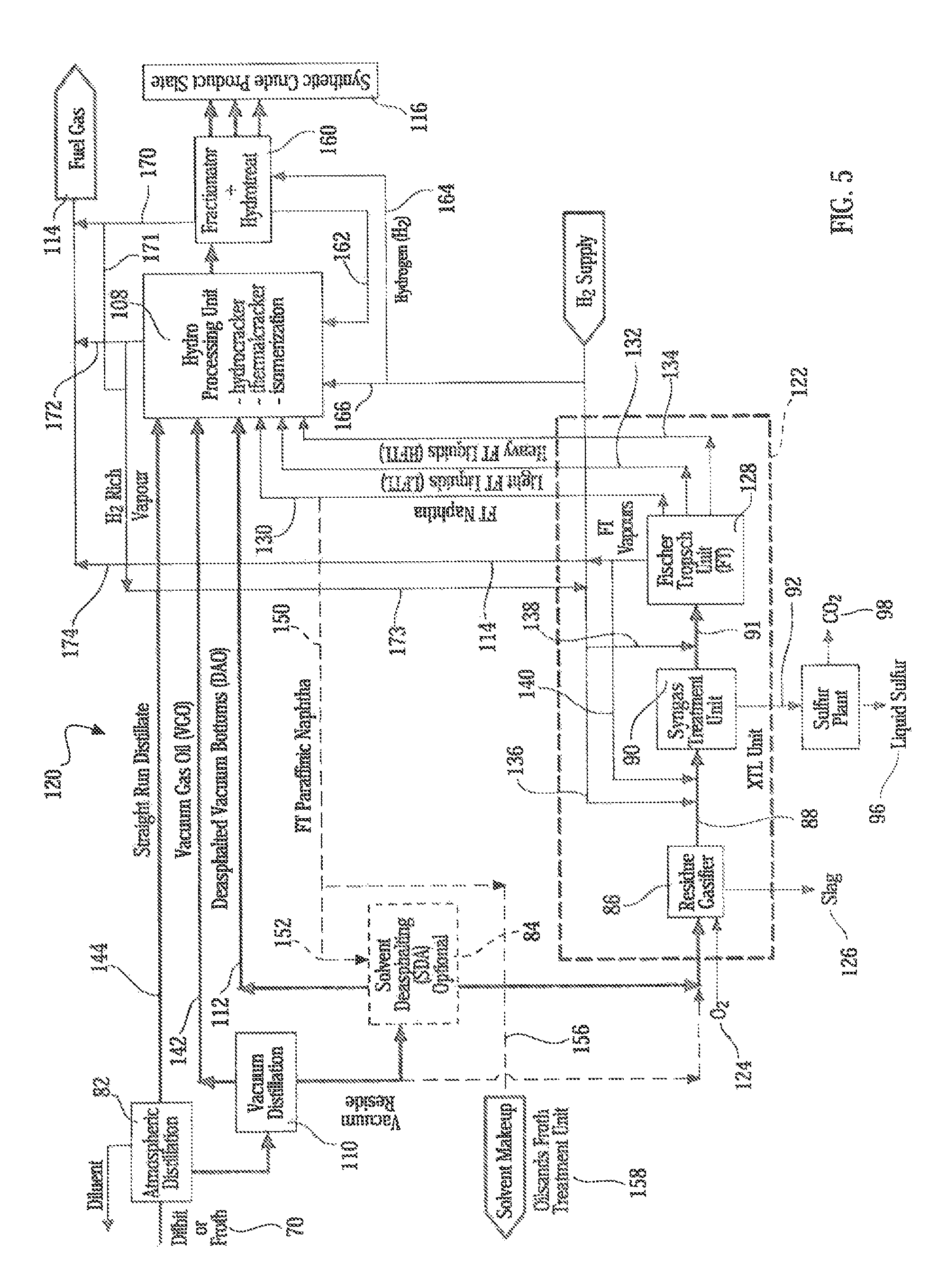
[0028]One object of the present invention is to provide an improved heavy oil and bitumen upgrading methodology for synthesizing hydrocarbons with a substantially increased yield without the production of waste byproducts such as petcoke or residuum.
[0038]The present disclosure amalgamates a series of known unit operations into a much improved synthesis route for a high yield, high quality production of synthetic hydrocarbons and co-production of commercially valuable co-products from by-products of this synthetic route. Integration of a Fischer-Tropsch process, and more specifically the integration of a Fischer-Tropsch process with a hydrogen rich syngas generator which uses FT naphtha, FT LPG and / or FT / upgrader vapours as primary fuel in combination with natural gas, in a steam methane reformer (SMR) and / or an autothermal reformer (ATR) results in a superior sweet synthetic crude oil which is synthesizable in the absence of petcoke and residuum.
[0042]It was further discovered that employing an autothermal reformer (ATR) as a sole hydrogen rich syngas generator or in any series or parallel combination with the SMR or as a hybrid combination of an ATR / SMR referred to as a XTR, significant benefits resulted in a greater than 200% increase in the FT middle distillate synthetic hydrocarbons. Feedstreams for the ATR or XTR consist of FT naphtha, FT LPG, FT vapours, H2 rich upgrader vapours, Upgrader excess LPG, CO2, O2 and natural gas.

Problems solved by technology

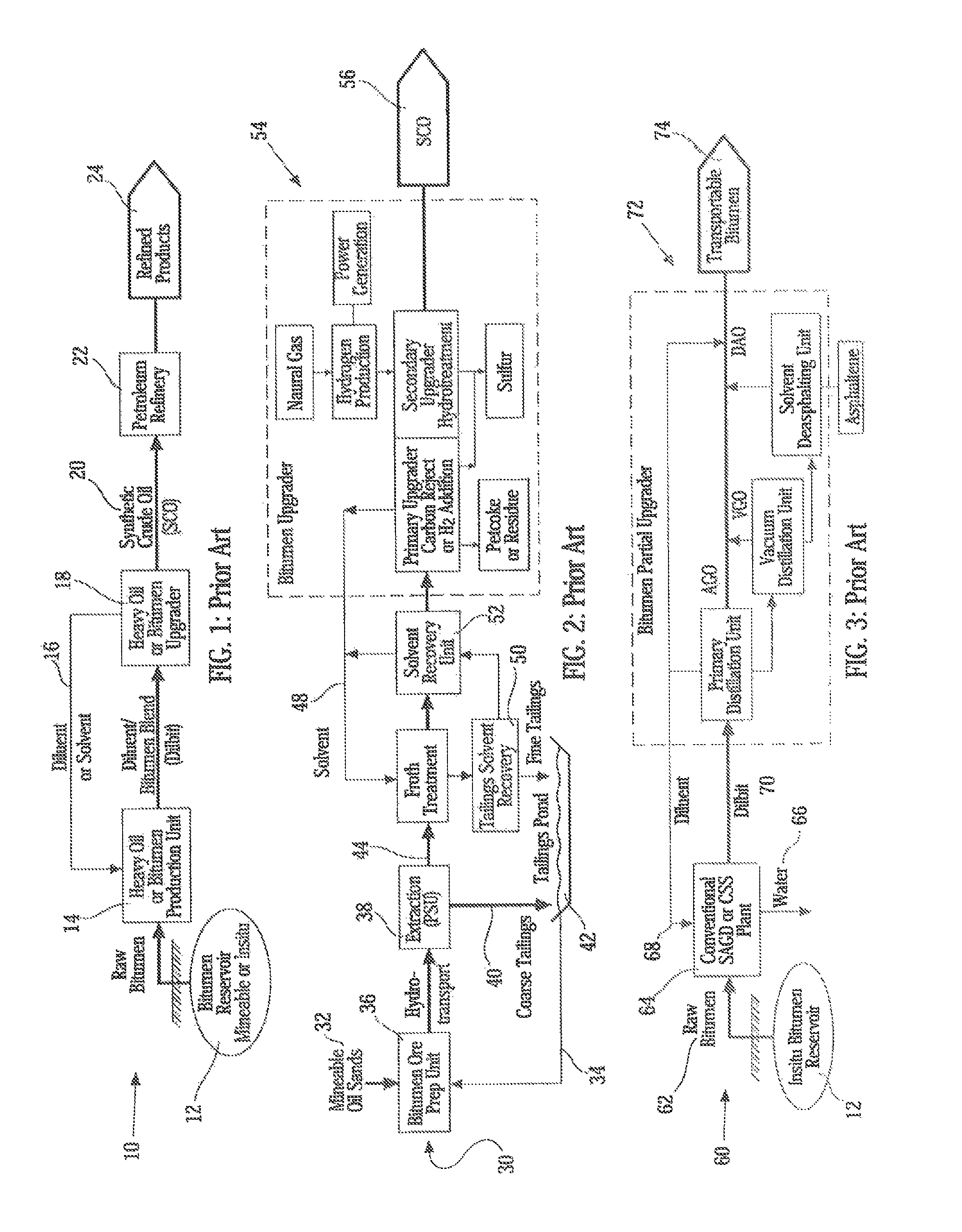
Further, refineries are not suited to processing heavy oil, bitumen etc. and thus the viscosity, density and impurity content, such as heavy metals, sulfur and nitrogen, present in such heavy materials must be altered to permit refining.
One of the problems with heavy oil and bitumen upgrading is that the asphaltenes and the heavy fraction must be removed or modified to create value and product yield.
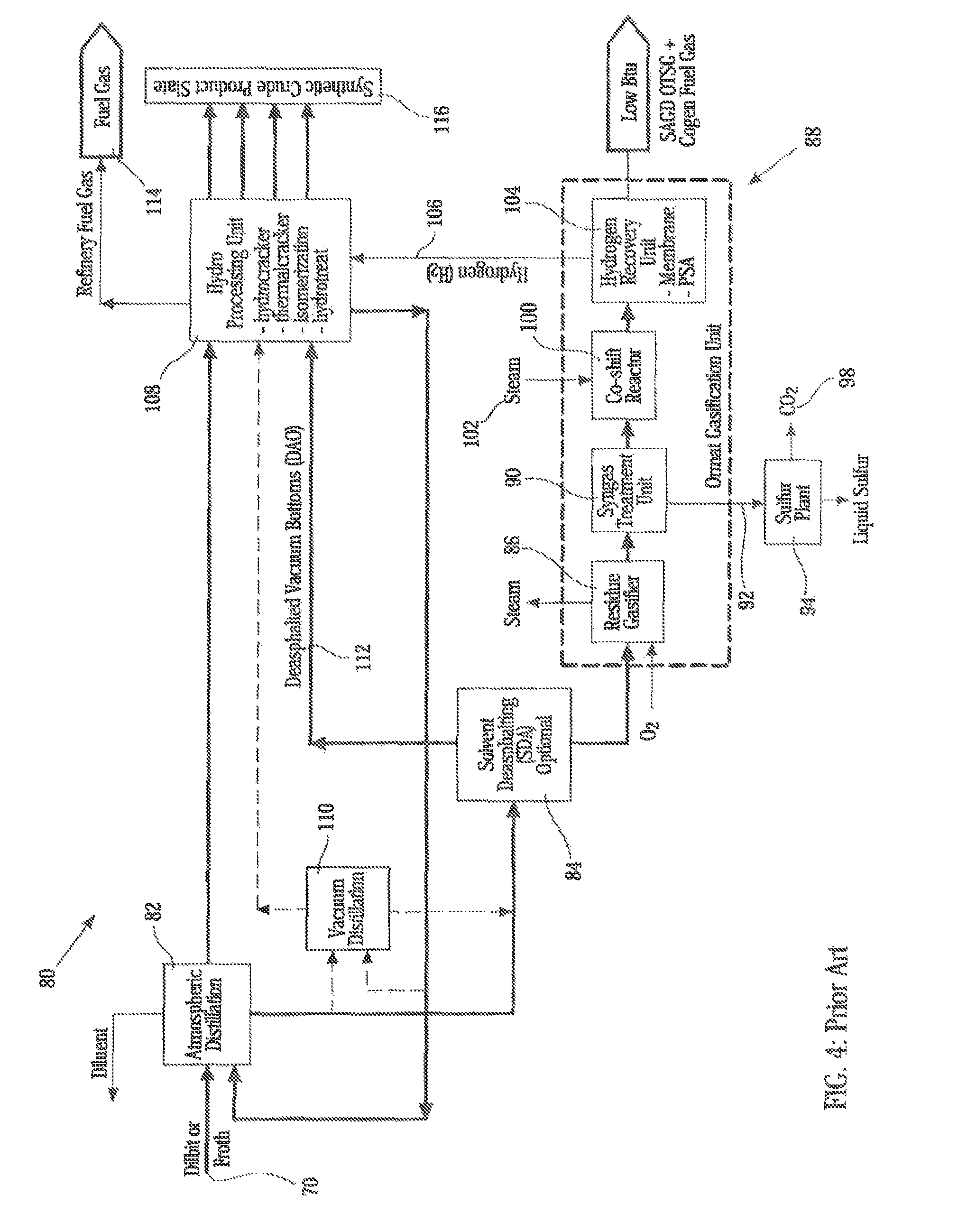
Typical upgraders exacerbate the problem by the formation of petcoke or residuum which results in undesirable waste material.
This material, since it cannot be easily converted by conventional methods, is commonly removed from the process, reducing the overall yield of valuable hydrocarbon material from the upgrading process.
The overall process is quite effective, however, it does not take advantage of the conversion of synthesized streams which are useful for introduction into the hydroprocessing unit for production of synthetic crude, the recycling of unique streams for use in the upgrader, nor is there any teaching specifically of the integration of the Fischer-Tropsch process or the recognition of the benefit to the process of using a SMR and / or ATR in the process circuit to maximize SCO yields and reducing dependence on natural gas.
Similar to the process taught in U.S. Pat. No. 7,407,571, this process has utility, however, it limits the conversion of the otherwise wasteful asphaltene to production of solid fuel or pellets or conversion to syngas for fuel, hydrogen or electric power production.
This document is primarily concerned with hydroconversion of heavy hydrocarbon, while not being suitable for bitumen upgrading.
It also fails to provide any teaching regarding the use of Fischer-Tropsch process, usefulness of recycle streams, hydrogen generation or other valuable and efficient unit operations critical to successful upgrading of raw bitumen.
The method does not incorporate the particularly valuable Fischer-Tropsch process or provide a unit for effecting the Fischer-Tropsch reaction and further, the method is limited by the use of the catalyst which would appear to be quite susceptible to sulfur damage and from this sense there is no real provision for handling the sulfur in the bitumen.

Method used


Image

  • Process for co-producing commercially valuable products from byproducts of heavy oil and bitumen upgrading process
  • Process for co-producing commercially valuable products from byproducts of heavy oil and bitumen upgrading process
  • Process for co-producing commercially valuable products from byproducts of heavy oil and bitumen upgrading process

Examples


example 1

[0109]This example describes the design basis of a co-production Methanol Plant 302, whereby a portion of about 356 MMSCFD of stream 190c is removed from the Fischer-Tropsch synthesis feed and directed as the base feed to unit 302. It is further combined with about 656 TPD CO2 from by-product stream 98a and about 40.6 MMSCFD H2 from stream 164, the result would be the optimum feed for co-production of 5,000 TPD or 1,800,000 TPY of Methanol by-product. This is the current world scale commercial methanol plant.[0110]a) Partial Stream 190c 356 MMSCFD or 39,035 moles / hr syngas with H2:CO=2.0[0111]b) Partial Stream 98a 656 TPD CO2 or 1370 moles / hr CO2 [0112]c) Partial Stream 164 40.6 MMSCFD H2 or 4452 moles / hr H2 [0113]d) The total syngas to Unit 302 44,856 moles / hr, or 67.94% H2, 29.06% CO, 3.0% CO2 [0114]e) Therefore, optimum syngas to Unit 302=(67.94-3.0) / 29.06+3.0)=2.03[0115]f) Total stream of 13,011 moles / hr CO+1,370 moles / hr CO2+30,475 moles / hr H2 results in 14,381 moles / hr CH3OH o...

example 2

[0116]This example describes a design basis of a co-production Ammonia Plant 310, whereby the Air Separation Unit produces 2100 TPD of high purity oxygen 124 for the upgrader use. The subsequent by-product of nitrogen results in 8,300 TPD N2 as stream 308. A portion of about 306 MMSCFD H2 from stream 164 is combined with 4,194 TPD N2, the result would be the optimum feed for the co-production of 5,000 TPD or 1,800,000 TPY of Ammonia by-product. This is the current world scale commercial ammonia plant.[0117]a) Partial Stream 308 consisting of 4,194 TPD N2 or 11,333 moles / hr[0118]b) Partial Stream 164 consisting of 306 MMSCFD H2 or 33,553 moles / hr H2 [0119]c) The total feed stream to Unit 310 of 44,886 moles / hr, or 25.2% N2 and 74.8% H2 [0120]d) 11,333 moles / hr N2+33,553 moles / hr H2 results in 22,666 moles / hr NH3 or about 453,320 lb / hr=5,000 TPD or 1,800,000 TPY ammonia

example 3

[0121]This example describes a design basis for a co-production Urea Plant 314, whereby a portion of the ammonia production 312 and additional by-product CO2 from the upgrader / refinery (98 a, b or c) is combined to produce urea fertilizer.[0122]a) Partial Stream 312 consisting of 4,202 TPD NH3 or 19,048 moles / hr[0123]b) Remaining portion of Stream 98a consisting of 544 TPD CO2 and Partial Stream 98c consisting of 4017 TPD CO2 for total of 4,561 TPD CO2 or 9,524 moles / hr CO2 [0124]c) The total feed stream to Unit 314 of 28,572 moles / hr, or 66.7% NH3 and 33.3% CO2 [0125]d) 19,048 moles / hr NH3+9,524 moles / hr CO2 results in 9,524 moles / hr NH2CONH2 or about 628,584 lb / hr=6,800 TPD or 2,400,000 TPY urea

[0126]The examples described above illustrate how the integration of the co-product units can recover a significant portion of the upgrader / refinery GHG CO2 emissions and co-produce 5,000 TPD Methanol and 5,000 TPD Ammonia or 6,800 TPD of Urea, and result in a “Near Zero GHG Emissions World...


PUM

PropertyMeasurementUnit
pressureaaaaaaaaaa
viscosityaaaaaaaaaa
densityaaaaaaaaaa

Abstract

The present invention is directed to modifications of bitumen and heavy oil upgrading and refining processes to synthesize synthetic crude oil and other valuable synthesized hydrocarbon products in an efficient manner along with the production of commercially valuable co-products from by-products formed by the upgrading process.

Description

CROSS-REFERENCE TO RELATED APPLICATIONS[0001]This application is a continuation-in-part of U.S. application Ser. No. 13 / 091,025, filed Apr. 20, 2011. The contents of the aforementioned application is hereby expressly incorporated by reference in its entirety and for all purposes.TECHNICAL FIELD[0002]The present invention relates to modifications of bitumen and heavy oil upgrading and refining processes to synthesize synthetic crude oil and other valuable synthesized hydrocarbon products in an efficient manner along with the production of commercially valuable co-products from by-products formed by the upgrading process.BACKGROUND OF THE INVENTION[0003]It is well established that certain forms of hydrocarbons require upgrading in order to either transport them or enhance value for sale. Further, refineries are not suited to processing heavy oil, bitumen etc. and thus the viscosity, density and impurity content, such as heavy metals, sulfur and nitrogen, present in such heavy material...

Claims


Application Information

Patent Timeline
Patent Type & Authority Patents(United States)
IPC IPC(8): C07C27/00C10J3/00C10K3/06C10G2/00C07C29/151C07C273/04C01B3/38C07C1/04C01B21/087C01B32/50
CPCC01B21/087C01B3/384C07C1/0485C07C29/1518C07C273/04C10G2/30C10J3/00C10K3/06C01B3/382C10J2300/1659C01B2203/0233C01B2203/0244C01B2203/0283C01B2203/043C01B2203/0405C01B2203/062C01B2203/1047C01B2203/1082C10G2300/1022C10G2300/1077C10G2300/206C10G2300/42C10J2300/0913C10J2300/0959C01B32/50C10G7/00C10G9/00C10G21/003C10G45/00C10G45/58C10G47/00C10G67/049Y02P30/00Y02P30/40C01B3/34C01B3/501C01B3/52C01B3/56C01B2203/0205C01B2203/0255C01B2203/0475C01B2203/1211C01B2203/141
Inventor KRESNYAK, STEVE
Owner EXPANDER ENERGY
Learn More