

Plastic automotive mirrors
a mirror and plastic technology, applied in the field of mirrors, can solve the problems of stress crazing/cracking of the thick reflective layer, and achieve the effects of reducing radiation exposure, reducing abrasion resistance, and reducing abrasion resistan
- Summary
- Abstract
- Description
- Claims
- Application Information
AI Technical Summary
Benefits of technology
Problems solved by technology
Method used
Image

Examples
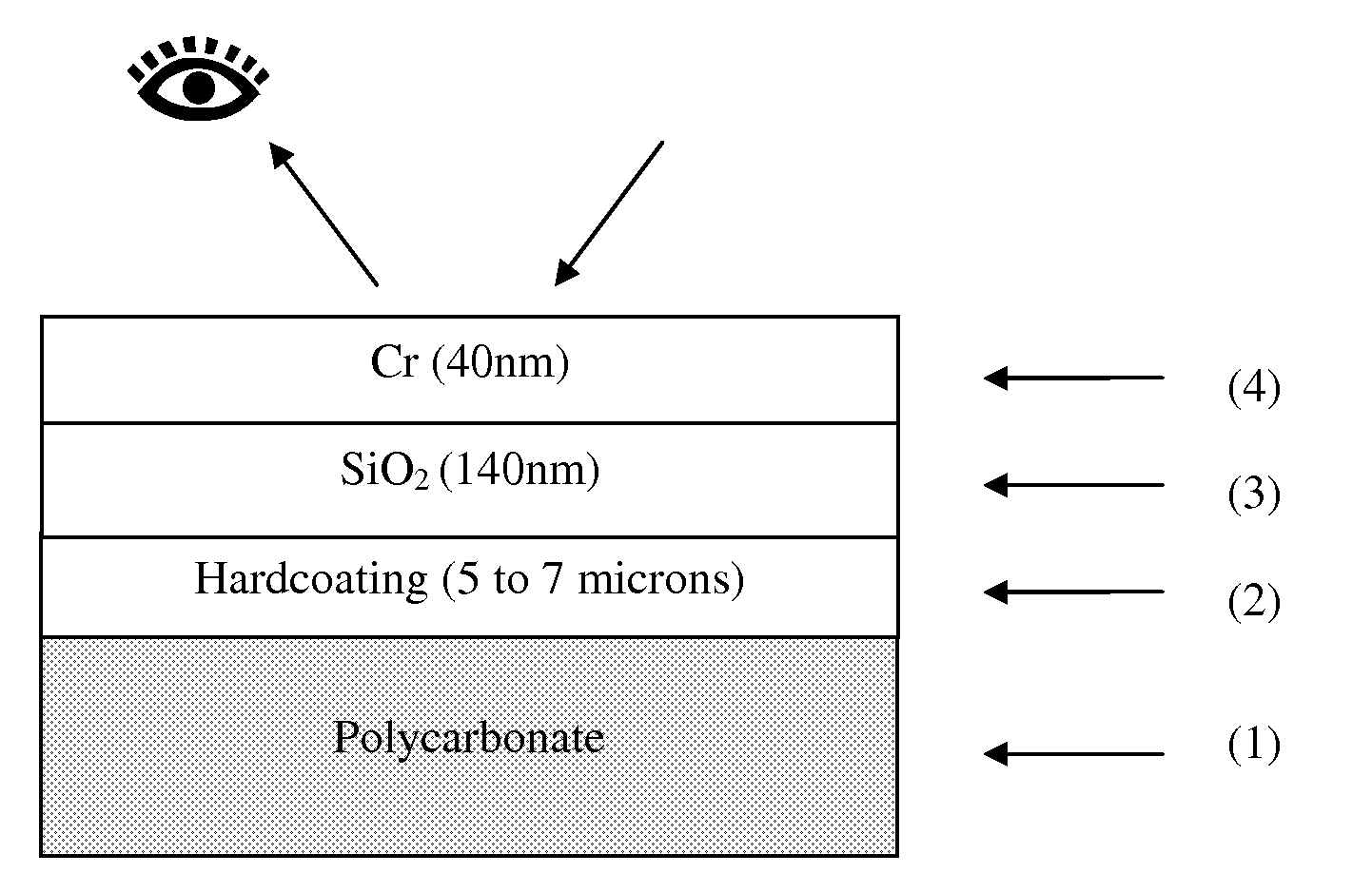
example 1
[0072]An injection moulded polycarbonate substrate is first cleaned through a commercial ultrasonic cleaning system with detergent. A final rinse in distilled water is required in a clean (dust free) environment. The substrate is then dip coated in a Momentive PHC-587B at a withdrawal rate of 10 mm / s. A flash-off time of 10 minutes allows solvents to slowly evaporate and the part to be largely tack free. The substrate is then moved to a curing oven for 45 minutes at 130° C. Subsequent coatings are performed within a 48 hour period so as to avoid aging / contamination of the hardcoating.
[0073]Samples are transferred to a holding oven maintained at 60° C., which ensures the plastic remains dry and helps reduce pump down times when transferred to the vacuum chamber.
[0074]The substrate is loaded into a batch type vacuum chamber, which consists of a single coating chamber in which the samples are placed, evacuated and coated. Within this chamber the samples were heated via an infrared heat...
example 2
[0078]An injection moulded polycarbonate substrate is first cleaned through a commercial ultrasonic cleaning system with detergent. A final rinse in distilled water is required in a clean (dust free) environment. The substrate is then dip coated in a SDC TSR 2626B at a withdrawal rate of 10 mm / s. A flash-off time of 10 minutes allows solvents to slowly evaporate and the part to be largely tack free. The substrate is then moved to a curing oven for 90 minutes at 130° C. Subsequent coatings are performed within a 48 hour period so as to avoid aging / contamination of the hardcoating.
[0079]Samples are transferred to a holding oven maintained at 60° C., which ensures the plastic remains dry and helps reduce pump down times when transferred to the vacuum chamber.
[0080]The substrate was loaded into an in-line type vacuum chamber, which consists of a multiple coating chambers. The samples were loaded into an airlock within which the samples were heated via an infrared heater to approximately...
example 3
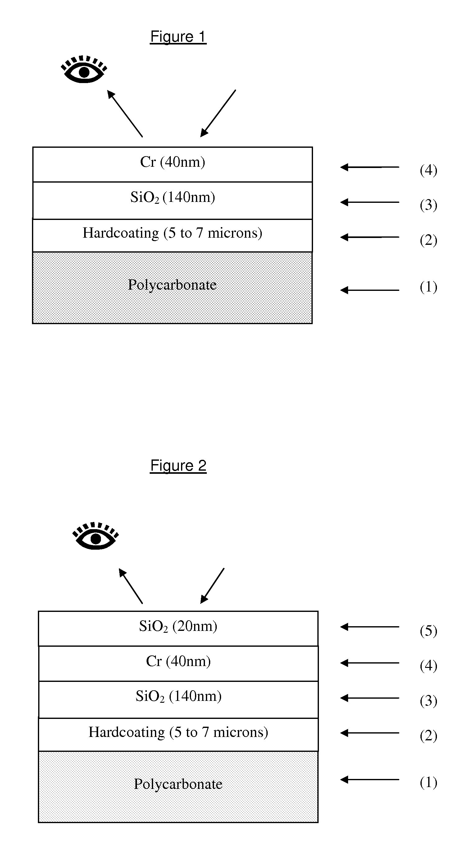
[0084]Another plastic mirror in accordance with the present invention, including a cap layer in the form of SiO2, was manufactured using a batch type vacuum chamber. It was found that further improvement to the abrasion resistance of the mirror can be obtained by depositing a cap layer in the form of SiO2.
[0085]The deposition conditions in this example were:
Intermediate Zone (Single Layer):
Silicon Target
Argon @ 32 sccm
Oxygen @ 16 sccm
Pressure=2.3e-3 mbar
Power @ 2.4 kW
Target to substrate distance=110 mm
Deposition speed=9 minutes
Thickness=130 nm
Chromium Target
Argon @ 120 sccm
Nitrogen @ 11 sccm
Pressure=4e-3 mbar
Power=1 kW
Target to substrate distance=110 mm
Time=2 minutes
Thickness=40 nm
Cap Layer:
Silicon Target
Argon @ 120 sccm
Oxygen @ 40 sccm
Pressure=2.3e-3 mbar
Power @ 2 kW
Target to substrate distance=110 mm
Deposition time=90 seconds
Thickness=10 nm
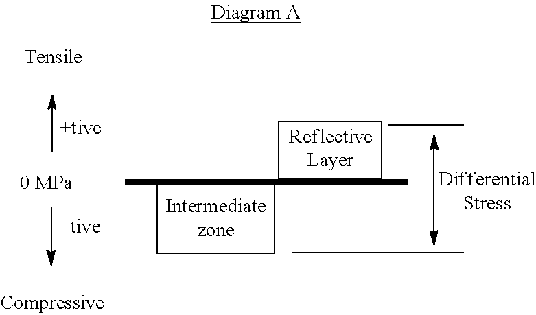
[0086]The measured residual stress of the layers was determined and the durability performance was tested. The results are set...
PUM
| Property | Measurement | Unit |
|---|---|---|
| reflectance | aaaaa | aaaaa |
| thickness | aaaaa | aaaaa |
| thickness | aaaaa | aaaaa |
Abstract
Description
Claims
Application Information