Storage cell, storage device, and magnetic head
a storage cell and magnetic head technology, applied in the field of storage cells, storage devices, and magnetic heads, can solve the problems of remarkable degradation of magnetic characteristics of magnetization pinned layers having perpendicular magnetic anisotropy, and achieve the effects of enhancing reliability, preserving stably recorded information in storage cells, and reducing power consumption of storage devices
- Summary
- Abstract
- Description
- Claims
- Application Information
AI Technical Summary
Benefits of technology
Problems solved by technology
Method used
Image
Examples
experiment 1
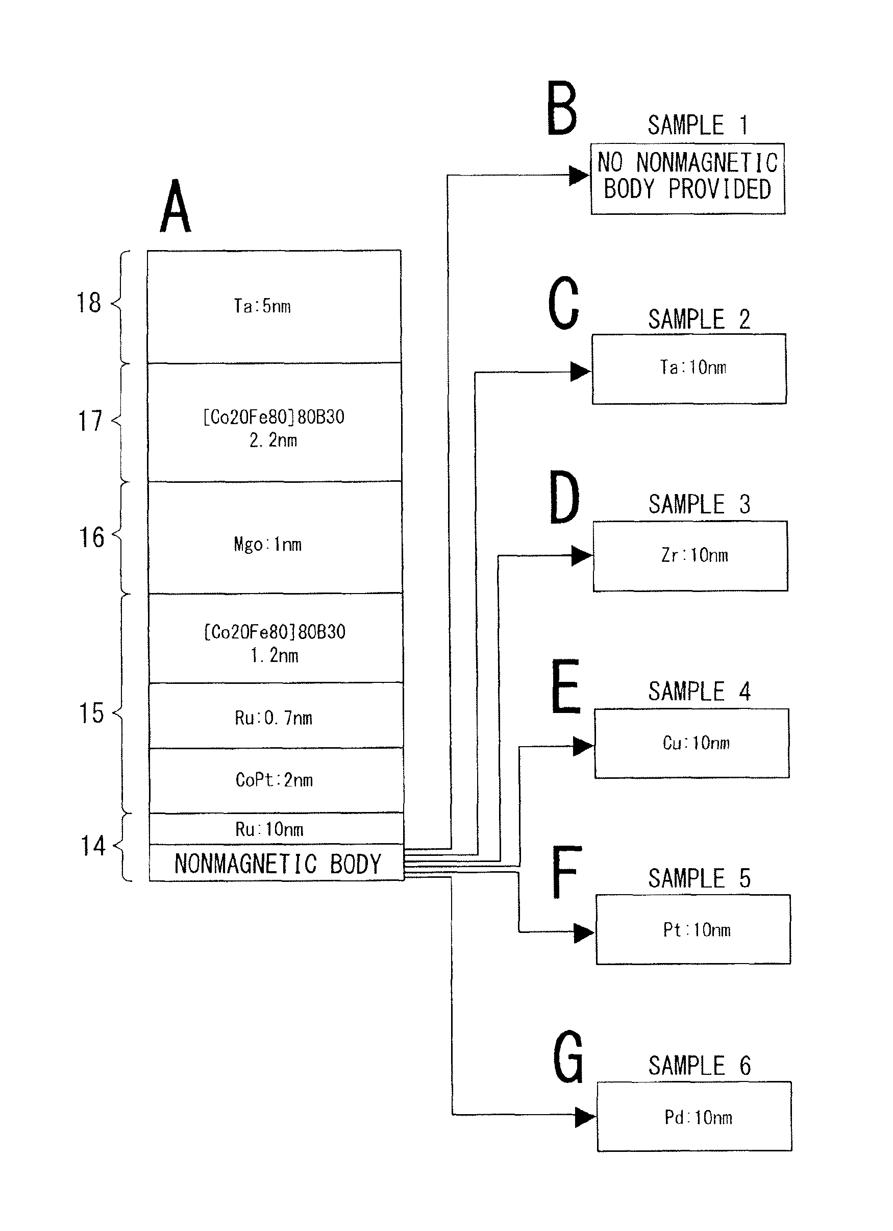
[0167]The present experiment is an evaluation of perpendicular magnetic anisotropy of the magnetization pinned layer 15 of the storage cell 3 in FIGS. 3A and 3B by measuring magnetization curves, demonstrating effects in a case that the base layer 14 has a lamination of Ru and a plurality of nonmagnetic bodies except Ru.
[0168]Samples include comparative examples in which the base layer 14 includes only Ru, a lamination of Ru and Ta as a material having a body-centered cubic lattice, or a lamination of Ru and Zr as a material having a lattice of hexagonal closest packing, and laminations of Ru and materials having face-centered cubic lattices.
[0169]Sample structures for the experiment are as follows. As illustrated in FIG. 4, in each sample, layers in the lamination structure from the substrate to the cap layer are as follows.[0170]the base layer 14 (A in FIG. 4): a laminated film of Ru and a plurality of nonmagnetic bodies except Ru, as will be described below.[0171]the magnetizatio...
experiment 2
[0194]The present experiment is to examine characteristics of the storage cell 3 in FIGS. 3A and 3B in a case that the base layer 14 under the magnetization pinned layer 15 has a laminated structure of Ru and a nonmagnetic body having a face-centered cubic lattice. Measurement of magnetoresistance curves and measurement of thermal stability from a reversal current value were carried out.
[0195]Sample structures for the experiment are as follows. As illustrated in FIG. 6, in each sample, layers in the lamination structure from the substrate to the cap layer are as follows.[0196]the base layer 14 (A in FIG. 6): a laminated film of Ru and a plurality of nonmagnetic bodies except Ru, as will be described below.[0197]the magnetization pinned layer 15 (A in FIG. 6): a laminated film of a 2 nm-thick Co—Pt layer, a 0.7 nm-thick Ru film, and a 1.2 nm-thick [Co20Fe80]80B30 film.[0198]the tunnel insulating layer (the intermediate layer 16) (A in FIG. 6): a 1 nm-thick magnesium oxide film (MgO)....
modification example
5. Modification Example
[0219]The structure of the storage cell 3 of the embodiment of the present disclosure is a configuration of a magnetoresistive effect element such as a TMR cell. The magnetoresistive effect element as the TMR cell may be applied not only to the above-described storage device but also to a magnetic head and a hard disc drive on which the magnetic head is mounted, and an integrated circuit chip, furthermore to various electronic apparatuses or electric apparatuses including a personal computer, a portable terminal, a mobile phone, and a magnetic sensor device.
[0220]As an example, FIGS. 7A and 7B illustrate an example in which a magnetoresistive effect element 101 having the structure of the above-described storage cell 3 is applied to a composite magnetic head 100. It is to be noted that FIG. 7A is a partly cut-away perspective view of the composite magnetic head 100 so as to illustrate its internal structure; and FIG. 7B is a cross-sectional view of the composi...
PUM
 Abstract
Description
Claims
Application Information
 - R&D
- Intellectual Property
- Life Sciences
- Materials
- Tech Scout
- Unparalleled Data Quality
- Higher Quality Content
- 60% Fewer Hallucinations
Browse by: Latest US Patents, China's latest patents, Technical Efficacy Thesaurus, Application Domain, Technology Topic, Popular Technical Reports.
© 2025 PatSnap. All rights reserved.Legal|Privacy policy|Modern Slavery Act Transparency Statement|Sitemap|About US| Contact US: help@patsnap.com


