Transformer-based power converters with 3D printed microchannel heat sink

a transformer and heat sink technology, applied in the direction of electrical equipment construction details, light and heating equipment, laminated elements, etc., can solve the problems of increasing heat dissipation, no heat flow path is particularly efficient, and substantial current harmonics that pollute the electric power generation and distribution system

Active Publication Date: 2016-01-05
CRANE ELECTRONICS INC
View PDF328 Cites 35 Cited by
  • Summary
  • Abstract
  • Description
  • Claims
  • Application Information

AI Technical Summary

Benefits of technology

[0015]A power converter apparatus may be summarized as including: an enclosure at least partially formed of a carbon fiber-reinforced polymer; and a power converter electronics assembly disposed within the enclosure, the power converter electronics assembly including: at least one magnetic component including a core having at least one winding surface and a winding wrapped around the core over the at least one winding

Problems solved by technology

However, this type of AC-DC conversion may lead to substantial current harmonics that pollute the electric power generation and distribution system.
For example, power converters for use in avionics typically must be lightweight and may need to occupy a small volume.
However, because the windings are often tightly wound and may be coated with an insulating material, heat generated internally must either transfer across several layers of insulation, travel through the core material (which may exhibit poor thermal conductivity) or travel along a winding conductive path and into the wiring or b

Method used


Image

  • Transformer-based power converters with 3D printed microchannel heat sink
  • Transformer-based power converters with 3D printed microchannel heat sink
  • Transformer-based power converters with 3D printed microchannel heat sink

Examples


Embodiment Construction

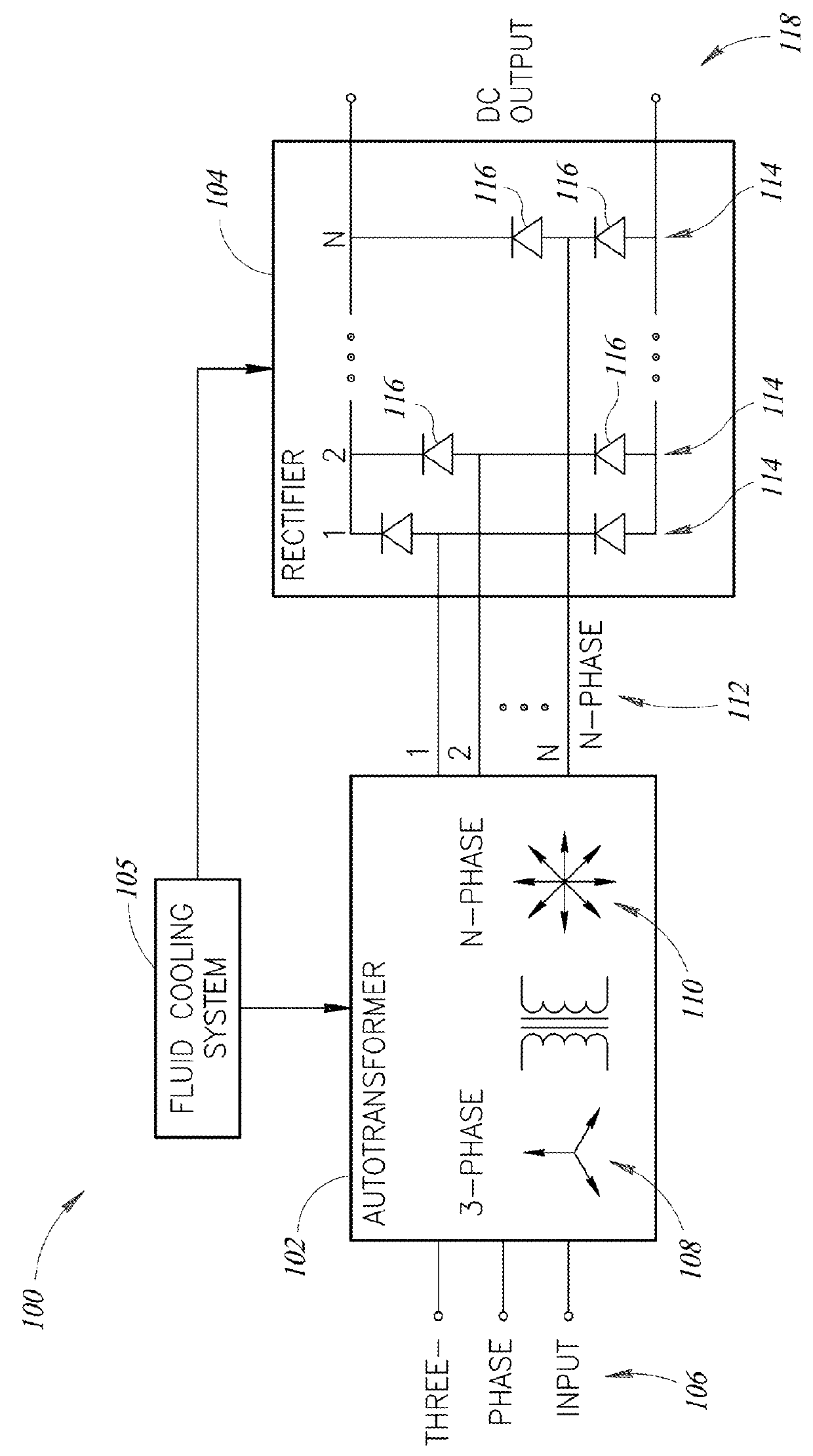
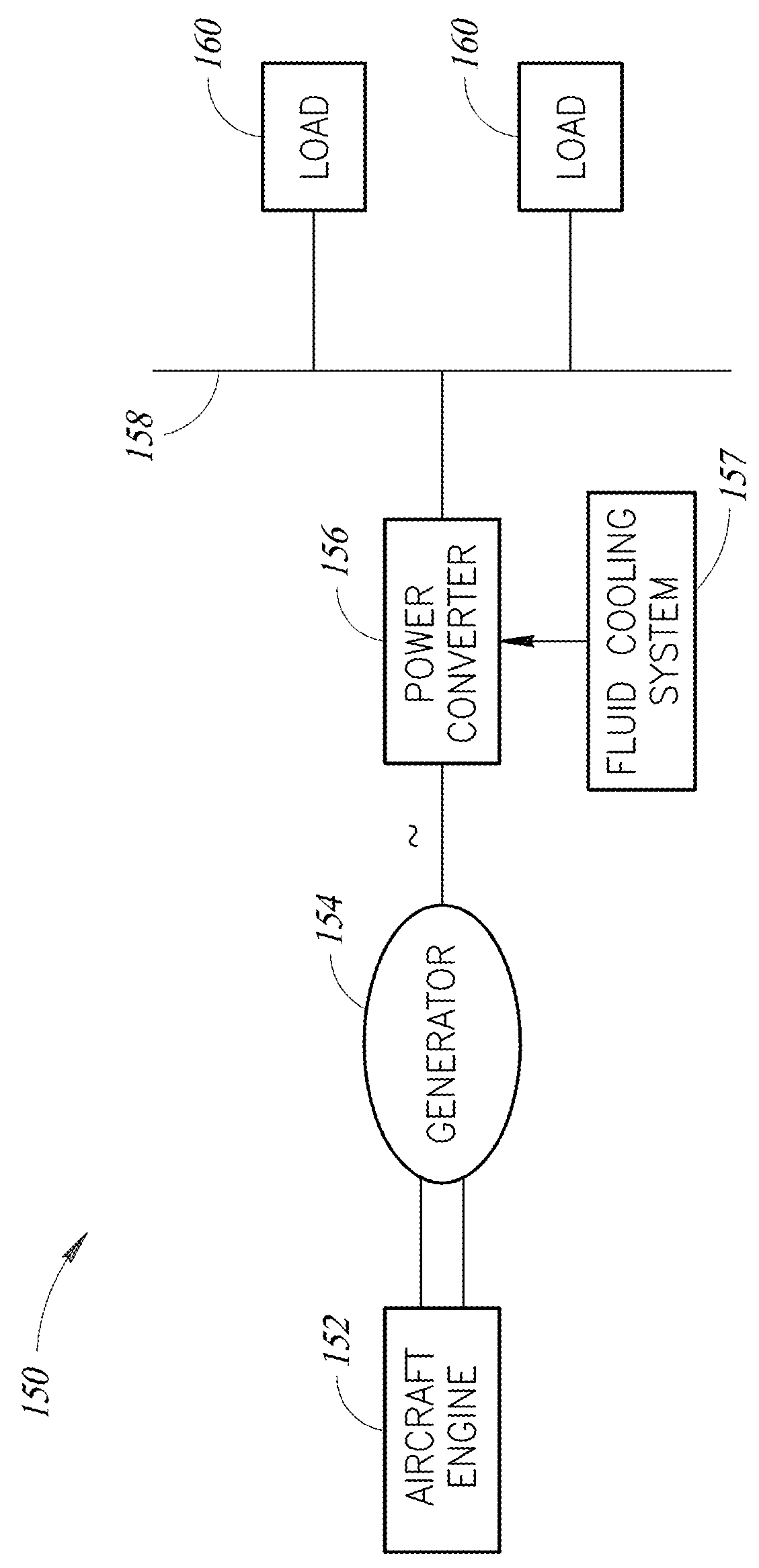
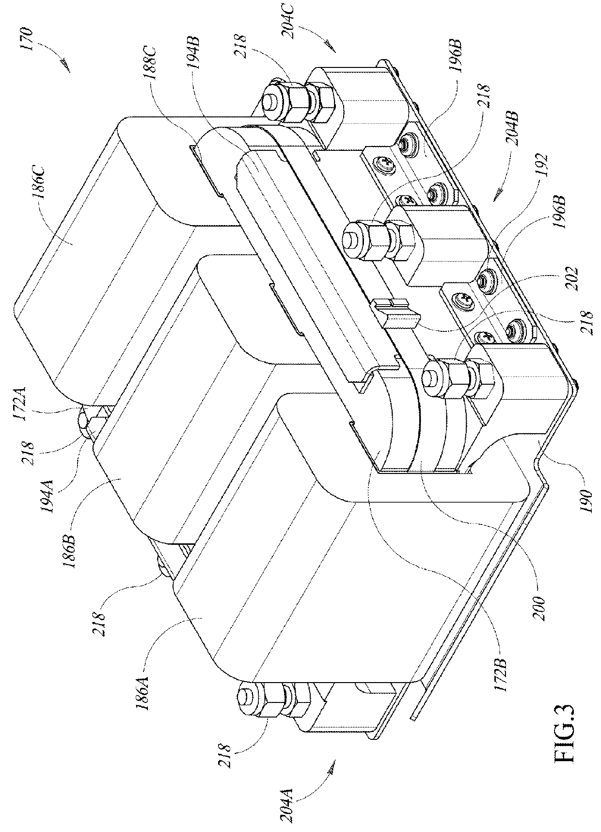
[0038]In the following description, certain specific details are set forth in order to provide a thorough understanding of various disclosed embodiments. However, one skilled in the relevant art will recognize that embodiments may be practiced without one or more of these specific details, or with other methods, components, materials, etc. In other instances, well-known structures associated with power electronics have not been shown or described in detail to avoid unnecessarily obscuring descriptions of the embodiments.

[0039]Unless the context requires otherwise, throughout the specification and claims that follow, the word “comprising” is synonymous with “including,” and is inclusive or open-ended (i.e., does not exclude additional, unrecited elements or method acts).

[0040]Reference throughout this specification to “one embodiment” or “an embodiment” means that a particular feature, structure or characteristic described in connection with the embodiment is included in at least one...


PUM

PropertyMeasurementUnit
Weightaaaaaaaaaa
Lengthaaaaaaaaaa
Flow rateaaaaaaaaaa

Abstract

Systems and methods that allow for weight and size reduction of electronics components, such as transformer rectifier units (TRUs) or autotransformer rectifier units (ATRUs), by providing a fluid cooling system is utilized to provide high heat dissipation for a transformer assembly of TRUs or ATRUs by providing a thermal interface at the windings of the transformer assembly, which are the hottest spots in such assemblies. The cooling system may include a fluid-cooled winding heat sink element or “finger,” which may be a thermally conductive bar (e.g., aluminum, copper) having microchannels therein positioned between the core and windings of a transformer or between turns of the windings of a transformer. Fluid passes through the microchannels of the heat sink element to provide direct cooling to the heat generating windings of the transformers. The heat sink element may be produced by an additive manufacturing technology.

Description

BACKGROUND[0001]1. Technical Field[0002]The present disclosure generally relates to systems, methods and articles for cooling components.[0003]2. Description of the Related Art[0004]Modern aircraft include generators that generate power during flight and provide the generated power to onboard aircraft electric power systems. The generators utilize rotation of the aircraft engine to generate AC power using various power generation techniques. Power generated in this manner may be 230V 400 Hz AC power, for example. While the aircraft is on ground, aircraft engines can be turned off, the onboard generator ceases generating power, and the onboard electric system instead may receive AC power from a ground cart. Power provided from the ground cart may be 115V 400 Hz AC power, for example.[0005]While the power sources provide AC power, aircraft components often require DC power instead of AC power. AC-DC power conversion may be accomplished with a plurality of diode pairs, where each pair ...

Claims


Application Information

Patent Timeline
IPC IPC(8): H05K7/20B33Y80/00B33Y50/00H01F41/00H01F27/10B33Y10/00
CPCH01F27/10H05K7/20254B33Y10/00B33Y80/00B33Y50/00H01F41/00F28F3/12B22F10/25B22F10/28B22F5/10B22F7/08H05K7/20927Y02P10/25
Inventor PARKER, ERNESTWANG, FANWHITE, JAMES WILLIAMPIERCE, MICHAEL ROBERTSTEPHENSON, RANDALLWILEY, DAVID L.
Owner CRANE ELECTRONICS INC
Why Eureka
Try Eureka