Method for manufacturing metal parts and molds and micro-roller used therefor

a technology of molds and metal parts, which is applied in the field of manufacturing a part and a mold and a micro-roller, can solve the problems of severe affecting modeling performance and accuracy, and achieve the effects of improving the formability of complex shape parts, improving the accuracy of side surfaces, and improving the formability and organizational performance of fused deposition layers

Active Publication Date: 2016-04-05
HUAZHONG UNIV OF SCI & TECH
View PDF6 Cites 6 Cited by
  • Summary
  • Abstract
  • Description
  • Claims
  • Application Information

AI Technical Summary

Benefits of technology

[0019]In a class of this embodiment, the micro-roller or the micro-extrusion unit is fixed on a head of the welding gun, and in the fused deposition modeling by layer by layer process, the micro-roller or the micro-extrusion unit move synchronically with the welding gun so that the side vertical roller among the micro-roller or the clamping plate of the micro-extrusion unit follows on the side of the welded and softened areas acting as a continuous casting crystallizer and a guide. Moreover, the flowing of the welded material in a molten pool can be limited by adjusting the pitch and angle according to the wall thickness and profile of the part or mold in order to avoid the flowing, dropping, crumbling problem caused by the gravity in occasions without support. Accordingly, it ensures the formability of a complex shape part, and can improve the accuracy of the side surface. If need to further improve the layer height accuracy, surface quality, formability and organizational performance of the fused deposition layer, the horizontal roller (or roller group) with a hole among the micro-roller or the clamping plate of the micro-extrusion unit should be always kept to contact with the semi-solid softened area near the rear of the melting pool. Through applying plastic deformation on this area, the accuracy and surface smoothness of the fused deposition layer are improved, the additional tensile strength of the weld bead and its adjacent area are reduced, and the deformation and cracks and improve the organizational performances are prevented.
[0020]In a class of this embodiment, the micro-roller or the micro-extrusion unit is fixed on a numerical control processing head or a robot wrist, and in the fused deposition modeling process, the numerical control processing head or the robot wrist moves synchronically with the welding gun so that the micro-roller or the micro-extrusion unit moves synchronically with the welding gun and the side vertical roller among the micro-roller or the clamping plate of the micro-extrusion unit follows on the side of the welded and softened areas. Moreover, the flowing, dropping, or crumbling problem for the complex shape part when there is no support and direct modeling can be avoid by adjusting the pitch and angle according to the wall thickness and profile of the part or mold. Accordingly, it ensures the formability of any complex shape part, and can improve the accuracy of the side surface. If need to further improve the layer height accuracy, surface quality, formability and organizational performance of the fused deposition layer, the horizontal roller (or roller group) with hole among the micro-roller or the clamping plate of the micro-extrusion unit can track the semi-solid softened area near the rear of the melting pool. Through applying plastic deformation on this area, the additional tensile strength of the weld bead and its adjacent area are reduced, the deformation and cracks are avoided, and the dimensional accuracy and improve the organizational performances are improved.
[0024]In the fused deposition modeling by layer-by-layer process, the micro-roller moves synchronously with the welding gun so that the side vertical roller follows on the side of the welded and softened areas acting as a continuous casting crystallizer and a guide. Moreover, the flowing of the welded material in molten pool can be limited by adjusting the pitch and angle according to the wall thickness and profile of the part or mold in order to avoid the flowing, dropping, crumbling problem caused by the gravity in the no support occasion. Accordingly, it ensures the formability of a complex shape part, and can improve the accuracy of the side surface. If need to further improve the layer height accuracy, surface quality, formability and organizational performance of the fused deposition layer, the horizontal roller with hole among the micro-roller should be always kept to contact with the semi-solid softened area near the rear of the melting pool. Through applying plastic deformation on this area, it can improve the accuracy and surface smoothness of the fused deposition layer, reduce the additional tensile strength of the weld bead and its adjacent area, and avoid the deformation and cracks and improve the organizational performances.
[0025]By using gas shielded welding (for example, TIG, plasma arc welding, metal active-gas welding, metal inert-gas welding) or high-powered laser modeling, this invention is used to cause the semi-molten / softened area and its adjacent area to occur roller forced deformation or squeeze forced deformation with the micro-roller or micro-extrusion unit installed behind the melting pool during the no support and dieless fused deposition modeling process for melting powders or wire material. Accordingly, it generates compression stress and compressive strain state in order to avoid cracking, reduce or eliminate the residual stress, and improve the organizational performance. Meanwhile, the flowing of the welded material in the molten pool can be limited by the micro-roller or clamping plate installed at the both sides of the molten pool, that is to say the rheoforming is limited, thus the dropping, flowing, crumbling problem caused by the gravity in the no support occasion can be avoid in order to ensure the formability of a complex shape part, and achieve the direct modeling of some parts or molds with complex shapes such as its sidewall with hanging angle. The above limit can also effectively reduce the ladder effect for the surface of the formed body and improve the modeling accuracy and surface quality, so that less or non milling process is needed and only grinding or polishing is needed to meet the requirements of the dimension and surface accuracy of the parts.
[0026]The method still maintains the advantages of the gas shielded welding fused deposition modeling method which having higher modeling efficiency, lower cost and much easier to meet the full density for the formed body than the high-powered laser deposition modeling method and electronic beam deposition modeling method. In addition, because the high-powered laser fused deposition modeling method belongs to the no support and dieless fused deposition modeling technology so that it also exists the same problems such as the formation of complex shape parts, crack, organizational performance as the plasma fused deposition modeling method, the invention can be used in the high-powered laser fused deposition modeling to solve the above problems. Therefore, by adopting this invention, the parts or molds from metal, intermetallic compound, metal ceramic, ceramic and its composite functionally gradient material can be high-quality, quickly, and low-cost obtained.
[0027]The method can also be used to repair or strength the surface of parts or molds, and can overcome the technical bottleneck that the subsequent finishing process is very difficult to execute for the repair layer or strength layer after repairing or strengthening.

Problems solved by technology

However, there are several problems with the existing methods: flowing, dropping or crumbling of fused deposition materials caused by the gravity, and cracking, deformation, large residual stress and unstable organization performance generated by rapid heating and rapid cooling during dieless fused deposition growth modeling severely affect modeling performance and accuracy.

Method used


Image

  • Method for manufacturing metal parts and molds and micro-roller used therefor
  • Method for manufacturing metal parts and molds and micro-roller used therefor

Examples


example 1

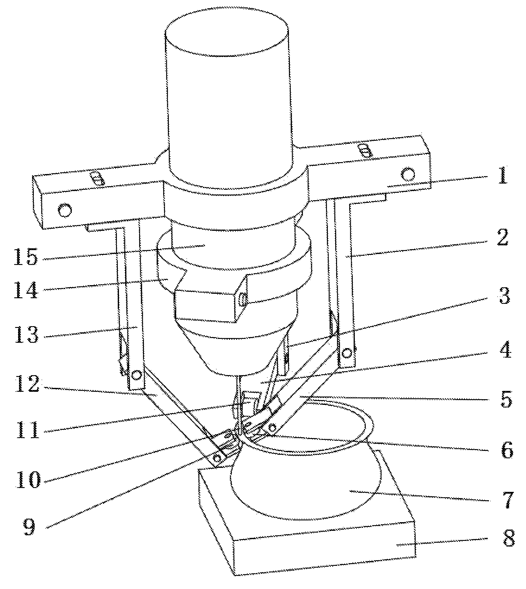
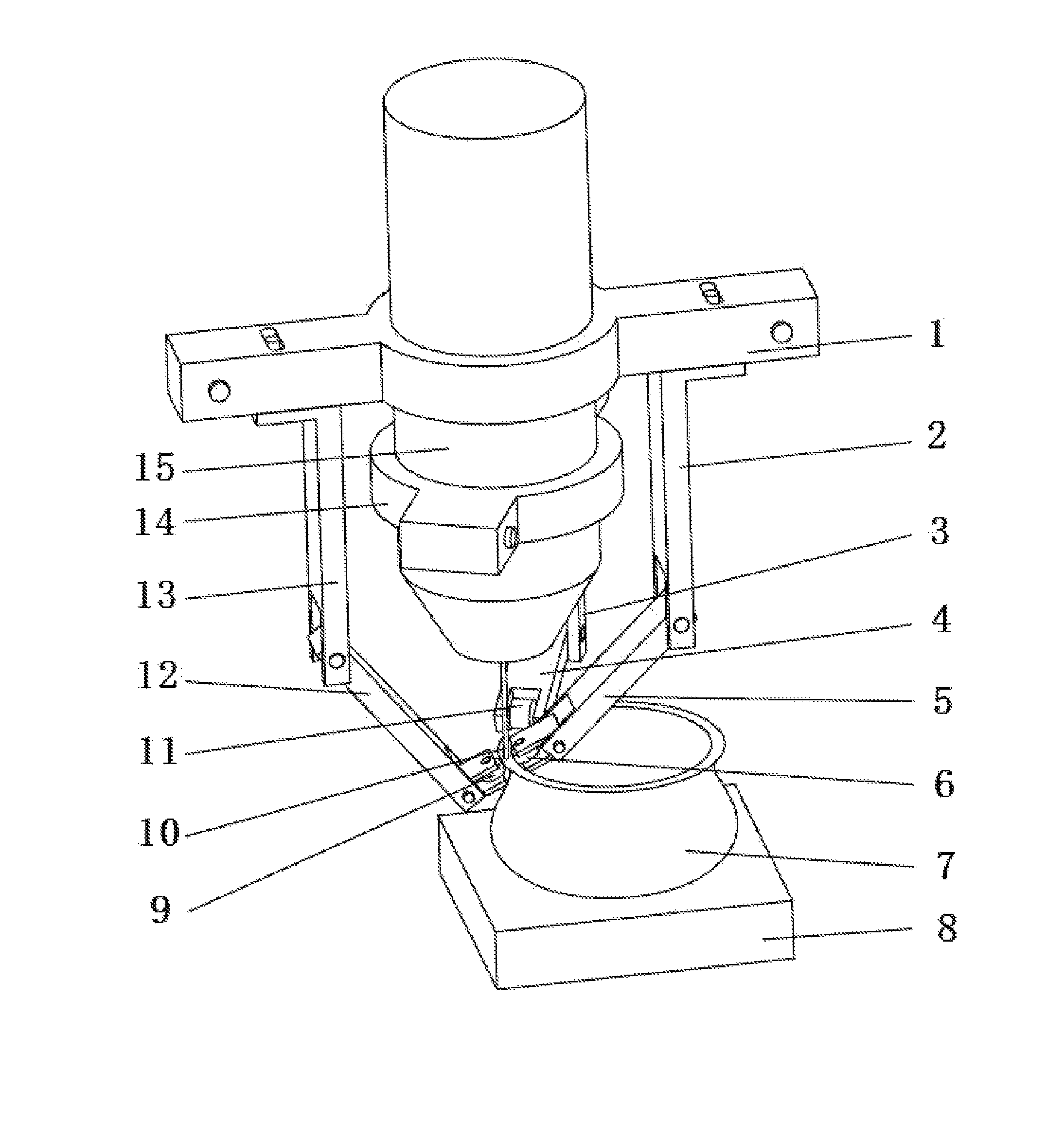
[0029]In the example, a TIG welding gun is used. The micro-roller fixed on the plasma welding gun move synchronously with the welding gun and the side vertical roller follows on the side of the melted and softened area. The welding current of the TIG welding gun is 60 A and uses a Fe—Ni—Cr alloy powder according to the operational performance requirements of the mold cavity to be fused deposition. According to the digital modeling path generated by the 3D CAD model of the mold, the fused deposition modeling and the shaping compressed by the micro-roller operation is synchronously excused layer by layer on the base. If the mold cavity is complex, a surface finishing process will be needed in the modeling process. Therefore, a milling and polishing operation is excused layer by layer or multi-layered segmented during the modeling process according to the milling and polishing path composited with the modeling path. This finishing process is excused alternately with the modeling proces...

example 2

[0030]In the example, a metal gas-shielded welding gun is used. The micro-extrusion unit fixed on the welding gun moves synchronously with the welding gun and the clamping plate follows on the side of the melted and softened area. The welding current of the metal gas-shielded welding gun is 50 A and uses an aluminum alloy wire material. According to the digital modeling path generated by the 3D CAD model of the part, the fused deposition modeling and the shaping compressed by the micro-extrusion unit operation is synchronously excused layer by layer on the base. Based on the requirements of the refinement of the grains and the development of the organizational performance, this compound field modeling process can be performed under vibration condition. Regarding a complex shape region of the part, a milling and polishing operation is excused alternatively during the synchronic process according to the milling and polishing path composited with the modeling path, until the modeling p...

example 3

[0031]In the example, a solid laser of 1000 W power is used. The micro-roller fixed on the laser head move synchronously with the laser head, so that the side vertical roller follows on the side of the melted and softened area and the horizontal roller with hole flexibly tracks the semi-solid softened area near the rear of the welding pool. According to the digital modeling path generated by the 3D CAD model of the part, the laser fused deposition modeling and the shaping compressed by the micro-roller operation is synchronously excused layer by layer on the base to process the high-temperature alloy part. If the part shape is complex, finishing process will be needed in the modeling process. Therefore, a milling and polishing operation is excused layer by layer or multi-layered segmented during the modeling process according to the milling and polishing path composited with the modeling path. This finishing process is excused alternately with the modeling process, until the modelin...


PUM

PropertyMeasurementUnit
currentaaaaaaaaaa
welding currentaaaaaaaaaa
plastic deformationaaaaaaaaaa

Abstract

A method for manufacturing parts and molds by: 1) slicing a three-dimensional CAD model of a part or mold; 2) planning a modeling path according to slicing data of the three-dimensional CAD model, whereby generating numerical control codes for modeling processing; and 3) performing fused deposition modeling of powders or wire material of metal, intermetallic compounds, ceramic and composite functional gradient materials by layer using a welding gun on a substrate layer via a numerical control gas shielded welding beam or laser beam according to a track specified by the numerical control code for each layer. A micro-roller or a micro-extrusion unit is installed at a contact area between melted and softened areas. The micro-roller or the micro-extrusion unit synchronously moves along with fused deposition area, which results in compressing and processing of the fused deposition area during the fused deposition modeling.

Description

CROSS-REFERENCE TO RELATED APPLICATIONS[0001]This application is a continuation-in-part of International Patent Application No. PCT / CN2011 / 072524 with an international filing date of Apr. 8, 2011, designating the United States, now pending, and further claims priority benefits to Chinese Patent Application No. 201010147632.2 filed on Apr. 15, 2010. The contents of all of the aforementioned applications, including any intervening amendments thereto, are incorporated herein by reference. Inquiries from the public to applicants or assignees concerning this document or the related applications should be directed to: Matthias Scholl P. C., Attn.: Dr. Matthias Scholl Esq., 14781 Memorial Drive, Suite 1319, Houston, Tex. 77079.BACKGROUND OF THE INVENTION[0002]1. Field of the Invention[0003]The invention relates to a method for manufacturing a part and a mold and a micro-roller related thereto.[0004]2. Description of the Related Art[0005]Dieless fused deposition modeling methods are widely ...

Claims


Application Information

Patent Timeline
Patent Type & Authority Patents(United States)
IPC IPC(8): G06F17/50B29C67/00B22F3/105B23K9/04B23K10/00B23K26/32B23K35/02B23K35/30B23K26/34
CPCB23K9/044B22F3/1055B23K10/006B23K26/32B23K26/322B23K26/342B23K35/0244B23K35/3053B23K35/3066B29C67/0055B22F2003/1056B22F2999/00B23K2201/34B23K2203/16B23K2203/50B23K2203/52B23P23/04B23K2101/35B23K2103/08B33Y10/00B33Y30/00B33Y50/00B23K2103/16B23K2103/50B23K2103/52B29C64/194B29C64/106Y02P10/25B22F12/86B22F10/66B22F10/25B22F10/18B22F3/18B22F3/20
Inventor ZHANG, HAIOUWANG, GUILAN
Owner HUAZHONG UNIV OF SCI & TECH
Why Eureka
Try Eureka