

Composite ferrite composition and electronic device
a technology of composite ferrite and electronic devices, which is applied in the direction of inorganic material magnetism, inductance, magnetic bodies, etc., can solve the problems of increasing dc resistance, difficult to reduce the dielectric constant of ni—cu—zn, and difficulty in applying the invention of patent document 1 to chip parts that are required for miniaturization, etc., to achieve excellent sinterability, high insulation resistance, and high permeability
- Summary
- Abstract
- Description
- Claims
- Application Information
AI Technical Summary
Benefits of technology
Problems solved by technology
Method used
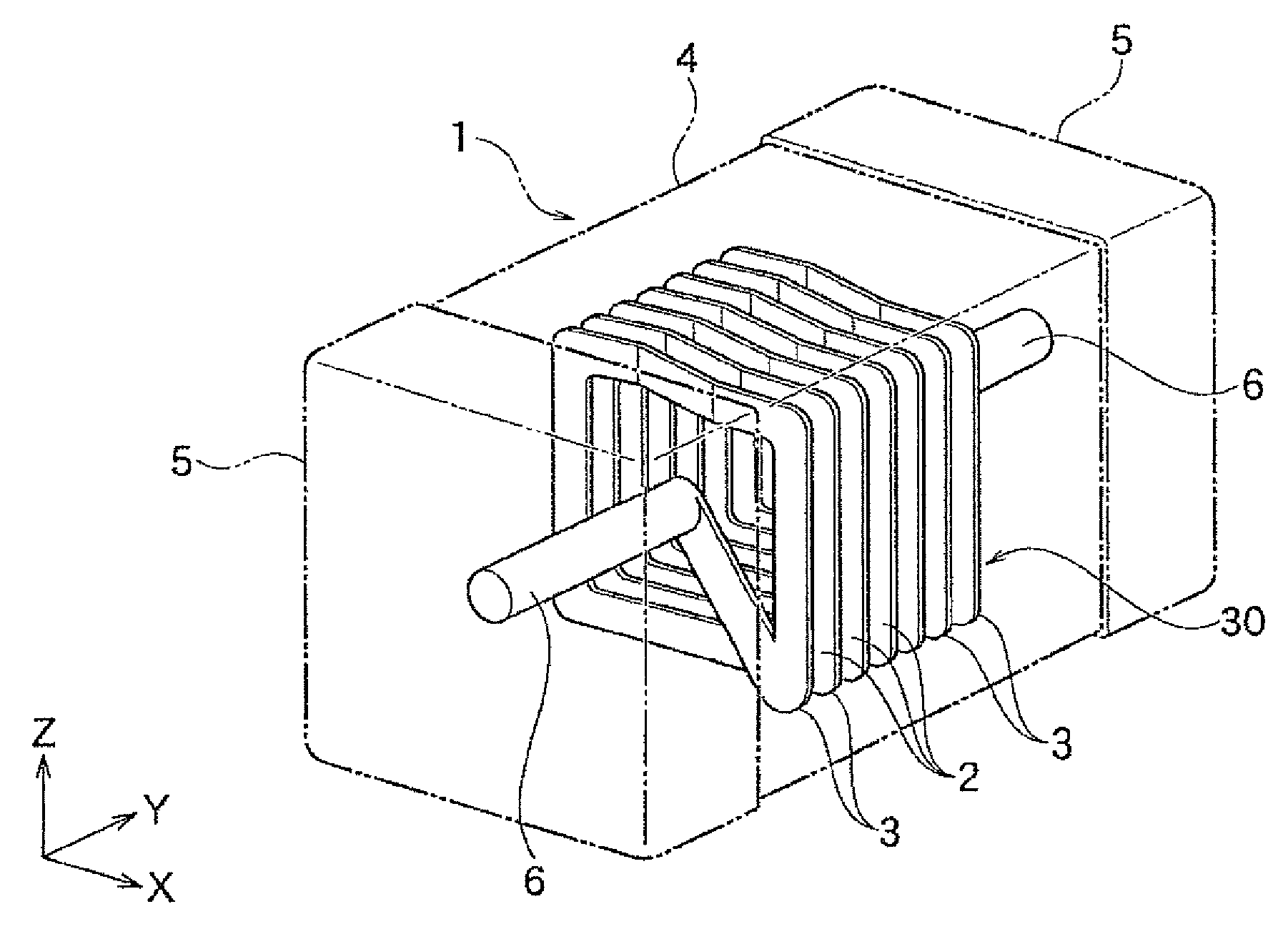
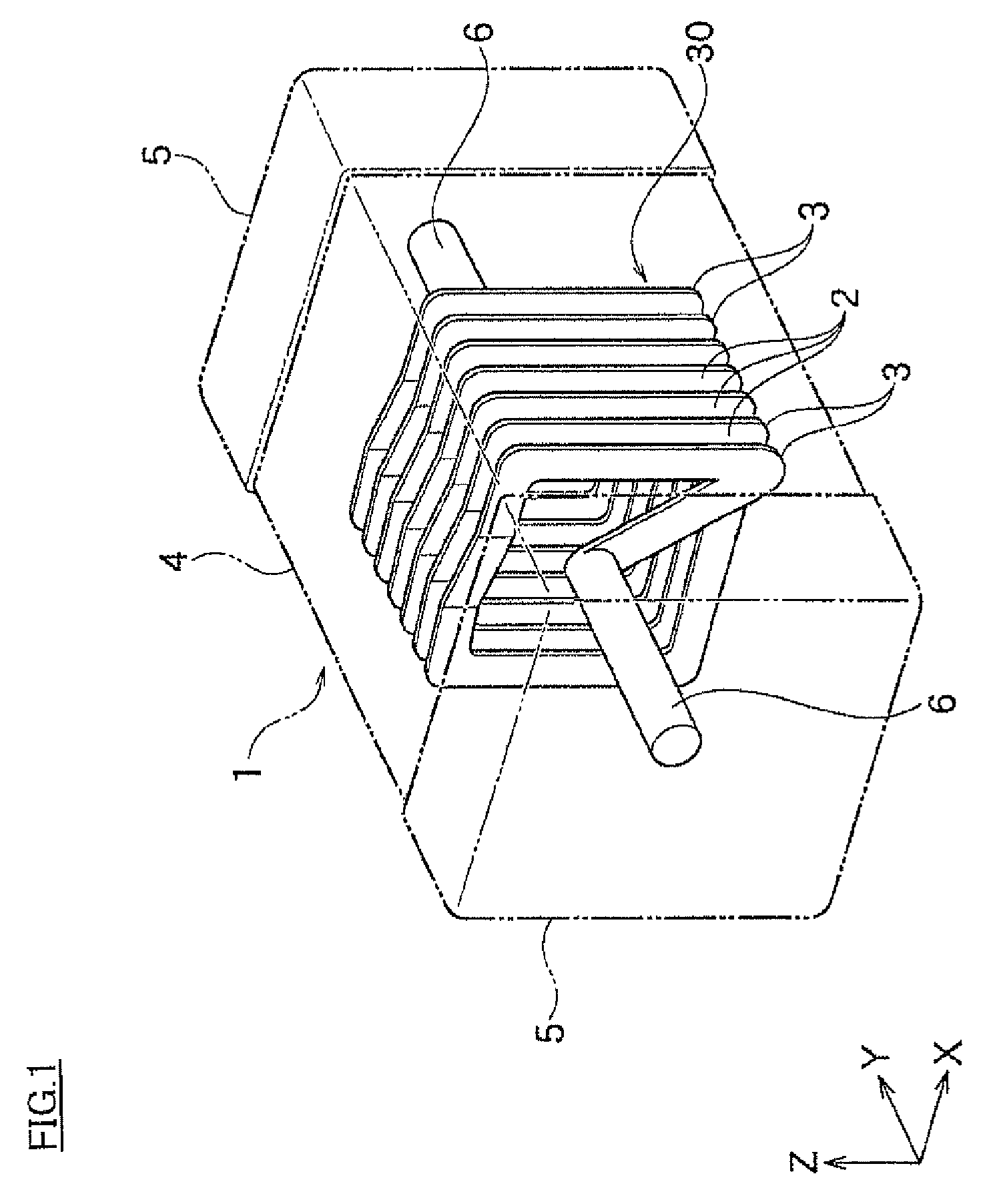
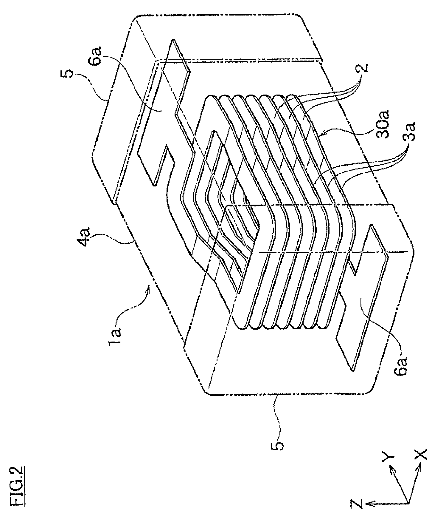
Image

Examples
example 1
[0070]First, as a magnetic material, Ni—Cu—Zn based ferrite (average particle size is 0.3 μm), that μ becomes 110 and ∈ becomes 14.0 when filing it alone at 900° C., was prepared.
[0071]Next, a non-magnetic material, that μ becomes 1 and ∈ becomes 6 when firing it alone at 900° C., was prepared. The non-magnetic material was prepared by mixing 2(0.98Zn.0.02CuO).SiO2 (average particle size is 0.5 μm) as a main component with SrO—SiO2—B2O3 based glass (average particle size is 0.5 μm) as a subcomponent so that the content of SrO—SiO2—B2O3 based glass becomes 3.8 wt % with respect to 100 wt % of the non-magnetic material. Further, as SrO—SiO2—B2O3 based glass, commercially available one was used.
[0072]Further, the above magnetic materials and the non-magnetic materials are respectively weighed so that the mixing ratio of them becomes as indicated in Table 1. After that, the mixture was wet-blended by a ball mill for 24 hours and the slurry thereby obtained was dried by a drying machine ...
example 2
[0083]Except that the main component composition of the non-magnetic material was changed as shown in Table 2, a sintered compact (composite ferrite composition) was produced and evaluated in the same way with sample 7 of example 1.
[0084]
TABLE 2General FormulaResonanceSpecifica(bZnO•cMgO•dCuO)•SiO2Relative DensityFrequencyDielectricResistanceSample No.abcd[vol %]Permeability[MHz]Constant[Ω· m]72.000.980.000.0297.002.81213.637.992.5E+08122.000.780.180.0496.122.70213.637.831.2E+08132.000.590.360.0595.913.09143.168.073.7E+07142.000.390.540.0796.023.2899.678.433.2E+08152.000.200.720.0891.043.5654.778.511.8E+09162.000.000.900.1073.002.10231.445.291.6E+07172.001.000.000.0083.151.80240.816.828.7E+0772.000.980.000.0297.002.81213.637.992.5E+08182.000.960.000.0497.963.02213.638.131.1E+08192.000.900.000.1097.233.14205.258.052.3E+07202.000.850.000.1598.523.35205.258.314.6E+06212.000.820.000.1899.143.53213.638.426.3E+05221.400.980.000.0288.351.53240.816.512.3E+07231.500.980.000.0291.671.97231.44...
example 3
[0087]Except that the amount of glass which is a subcomponent of the non-magnetic material was changed as shown in Table 3, a sintered compact (a composite ferrite composition) was produced and evaluated in the same way with sample 9 of example 1. The result is shown in Table 3.
[0088]
TABLE 3AmountRelativeResonanceSpecificSample of GlassDensityPerme-FrequencyDielectricResistanceNo.[wt %][vol %]ability[MHz]Constant[Ω· m]310.487.341.66240.815.628.1E+08320.590.391.69240.814.943.7E+09331.091.991.75240.816.095.5E+10342.095.751.77240.816.765.7E+0993.899.581.64240.817.141.0E+09367.496.941.63240.817.134.2E+083713.095.451.51240.817.122.5E+083815.094.661.48240.817.121.5E+083917.093.021.45240.817.127.0E+064020.091.411.32240.817.128.0E+05
[0089]As shown in Table 3, for the composite ferrite composition that the amount of glass which is a subcomponent of the non-magnetic material was within the range of the present invention, it could be confirmed that all of relative density, permeability, resona...
PUM
| Property | Measurement | Unit |
|---|---|---|
| temperature | aaaaa | aaaaa |
| dielectric constant | aaaaa | aaaaa |
| dielectric constant | aaaaa | aaaaa |
Abstract
Description
Claims
Application Information