Method for carbonization of crop straws

a carbonization technology and crop straw technology, applied in the field of pyrolysis carbonification technology for straws, can solve the problems of difficult and complete carbonization of vegetated feed, heavy labor intensity of workers, and complicated discharge of charcoal from the inner furnace, etc., to achieve easy transportation, high effective drying, preheating and pyrolysis.

Active Publication Date: 2016-04-26
SHANXI SANTIANYULONG AGRI TECH CO LTD
View PDF12 Cites 18 Cited by
  • Summary
  • Abstract
  • Description
  • Claims
  • Application Information

AI Technical Summary

Benefits of technology

[0006]An object of this invention is to solve the problems in prior art, such as low efficiency in pyrolysis carbonification, high cost for carbonification of crop straws and limited production scale. The present invention is to provide a method and a device for carbonification of crop straws so as to satisfy the requirements for pyrolysis carbonification of different crop straws.
[0008]In the method of producing charcoal from crop straws according to the present invention, the pyrolysis process and the carbonification process are separated by performing the pyrolysis and the carbonification processes in different units of the device, so that the production efficiency is improved. At the same time, the temperature of the crop straws in the pyrolysis pool is quickly raised by a controllable oxygen feeding method during the pyrolysis process, and then the crop straws are dried, preheated and quickly pyrolyzed.
[0015]In comparison with the prior art, the present invention has following features: (1) during the pyrolysis process, according to the difference in moisture content of the crop straws and the types of the crop straws, the oxygen feeding is controlled so that the crop straws are high effectively dried, preheated and pyrolyzed; (2) the pyrolysis process and the carbonification process are separated and accomplished in different units, so that the pyrolysis carbonification efficiency is greatly improved; (3) the combined structure design allows the pyrolysis carbonification device to be easily transported to the straw production place and quickly assembled. A problem of the general crop straws pyrolysis carbonification device being too large to transport or move is solved; (4) It is easily disassembled for transferring. According to the distribution of the crop straws, the crop straws pyrolysis carbonification device is timely disassembled to transport to a suitable operation region so as to reduce the high cost of crop straws transportation. At the carbonifying site of crop straws, the units are quickly assembled through a base plate, a frame and fasteners. When the carbonification in an operation region is finished, the device is disassembled for transporting to another operation region, and then such device is reassembled at that place for carbonification; (5) A gas settlement room is used in the crop straws pyrolysis process. The floating particles in the gas flow fall to the bottom of the settlement room through means in the settlement room. Wood tar and straw vinegar solution naturally condenses to adhere to the oil liquid collector and flows to the oil liquid collecting container, with the exhausted gas discharged harmlessly into the atmosphere. It is assured that the production procedure is harmless to the environment.
[0016]The crop straws charcoal produced by the present invention has various applications, e.g. for processing solid fuels utilized by rural residences to replace the fossil fuel; for modifying the soil by increasing the moisture content, the air permeability and the content of organic materials, so that the crop production is raised and diseases due to pests are decreased; for pre-processing the crop straws as raw materials of the methane production, resulting in the reduction of the volume of the crop straws and easy transportation and storage, and thus more economical and safe production of methane.

Problems solved by technology

Methods and Devices for carbonification of crop straws become much well developed during the technology development, but some drawbacks still exist.
Because the flame of vegetation thrown into the inner furnace seals the entrance of the furnace chamber of the inner furnace and thus the air cannot enter the lower portion of the inner furnace, the vegetation subsequently fed cannot be easily and completely carbonified.
After the carbonification process is finished, it is complicated to discharge the charcoal from the inner furnace, and auxiliary time for discharging, etc. is longer in comparison with the time for pyrolysis carbonification.
And the labor intensity of workers is heavy, and discharge cannot be performed until all the vegetation thrown into the inner furnace is carbonified and the temperature is reduced for a long time.
After a previous discharge, operations to fill, carbonify and discharge is once again taken, resulting in time consuming and lower production rate.
Furthermore, since the equipment takes a form of stationary structure, the cost for transporting crop straws is extremely high, and thus requirements of high efficiency, low cost and production in large scale cannot be fulfilled.
These limit the production rate of the carbonification of crop straws.
Since the carbonification device takes a form of stationary structure, the cost for transporting by-products of crop straws is extremely high, and the requirements of high efficiency, low cost and production in large scale cannot be fulfilled.
However, the production cycle is quite long from several days up to tens of days, the efficiency and the safety are low, and the economical profit is not good.
Solutions to problems of discharging the floating particles and poor environmental performance caused by the collection of wood tar and straw vinegar solution cannot be found, and thus it is not worth promoting.

Method used


Image

  • Method for carbonization of crop straws
  • Method for carbonization of crop straws
  • Method for carbonization of crop straws

Examples


Embodiment Construction

)

[0021]This invention is further described with reference to the Figures.

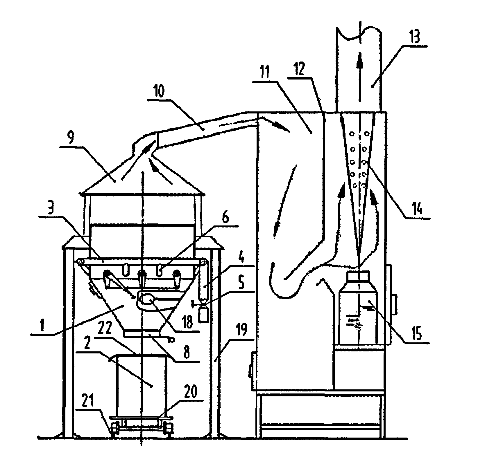
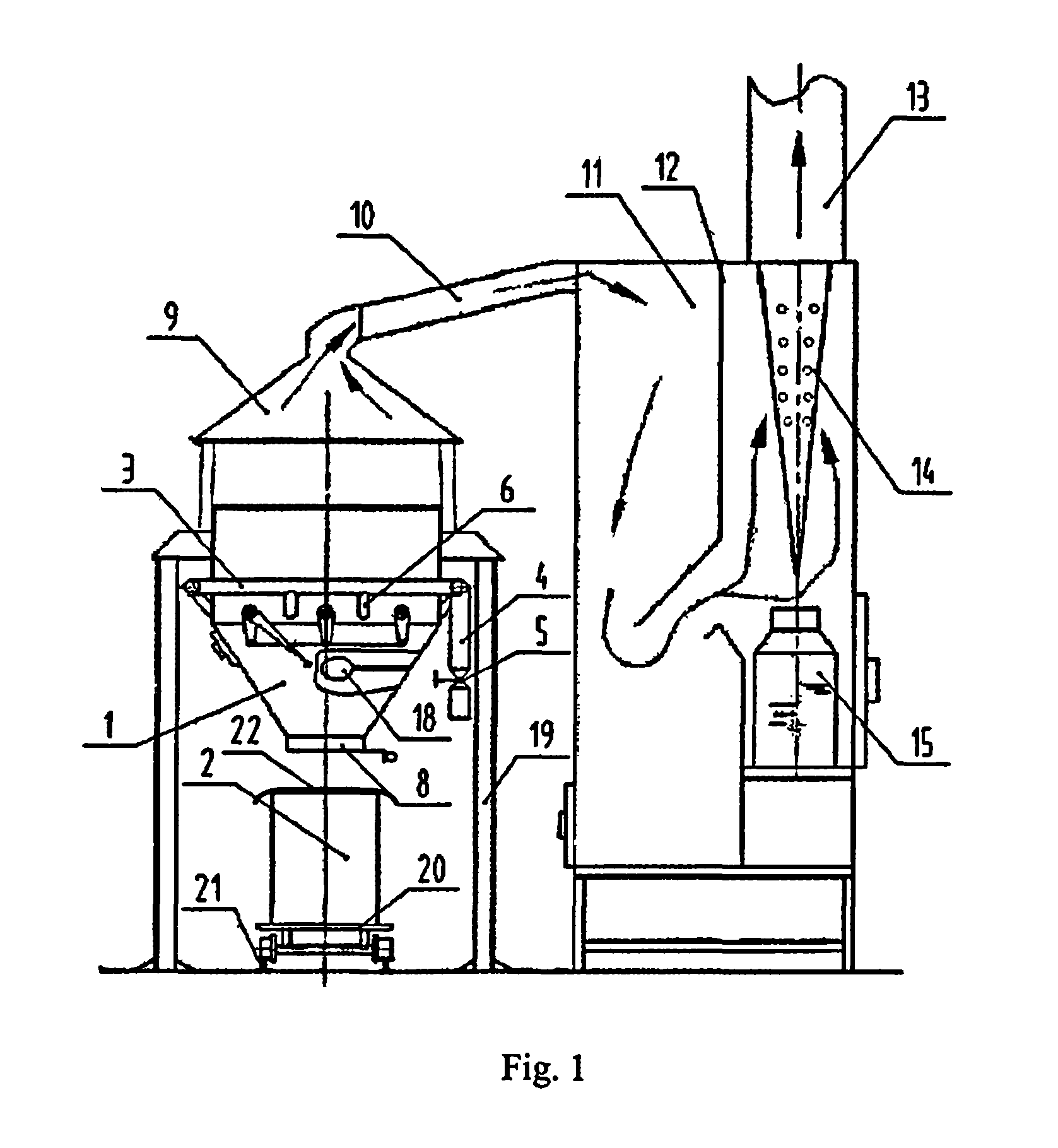
[0022]The present invention provides a combined crop straw carbonification method, in which a pyrolysis process is controlled by regulating the feeding of oxygen during the pyrolysis process, and pyrolysis and carbonification are respectively conducted in separate pyrolysis pool 1 and carbonification pool 2, wherein the straws are pyrolyzed in the said pyrolysis pool 1 and the pyrolyzed straws are discharged into the said carbonification pool 2 for carbonification.

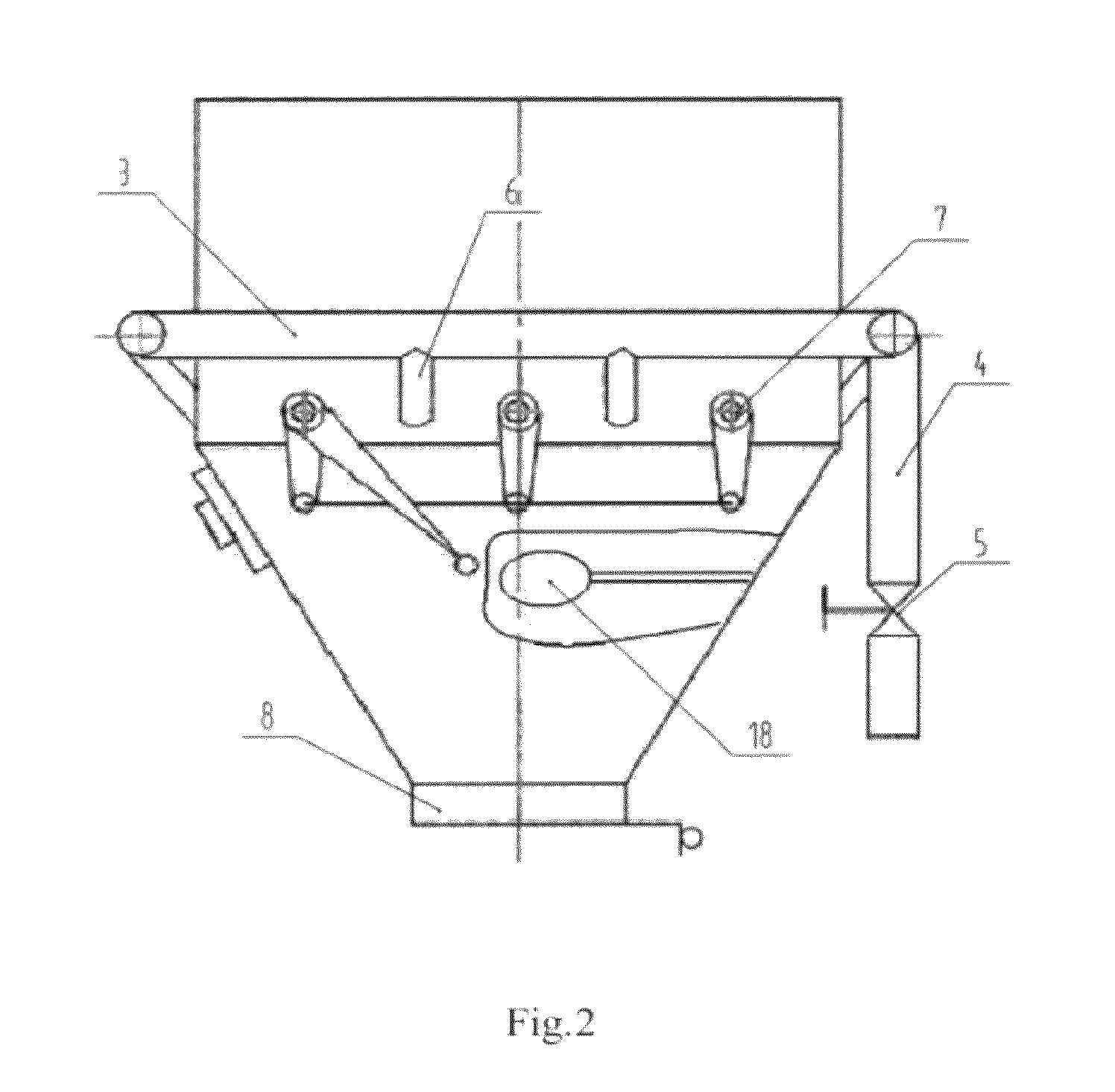
[0023]Corresponding to the above method, the present invention provides a crop straw carbonification device, comprising a pyrolysis pool 1, a carbonification pool 2 and a regulated oxygen feeding pipe 3, wherein a butterfly valve 5 for the oxygen feeding pipe is provided at an oxygen feeding port 4 of said regulated oxygen feeding pipe 3, and branch oxygen supply ports 6 connected to the regulated oxygen feeding pipe 3 are in communication with the py...


PUM

PropertyMeasurementUnit
temperatureaaaaaaaaaa
distanceaaaaaaaaaa
distanceaaaaaaaaaa

Abstract

The present invention is to provide a method for carbonification of crop straws and a device thereof. Pyrolysis process is controlled by regulating the feeding of oxygen during said pyrolysis process, and pyrolysis and carbonification are respectively conducted in separate pyrolysis and carbonification pools, wherein the straws are pyrolyzed in said pyrolysis pool and entered into said carbonification pool to be carbonified. The present invention can quickly raise the temperature of the pyrolysis process, shorten the time of the pyrolysis process, and improve the pyrolysis carbonification efficiency.

Description

FIELD OF INVENTION[0001]This invention relates to a field of pyrolysis carbonification technology for straws, and in particular, a method and a device for carbonification of crop straws.BACKGROUND OF THE ARTS[0002]Carbonification of crop straws plays an important role in the general utilization of straws. Methods and Devices for carbonification of crop straws become much well developed during the technology development, but some drawbacks still exist.[0003]For example, as described in the Chinese Patent ZL200510044136.3 titled with “carbonification process for vegetation with high temperature and floating oxygen”, which requires two furnace bodies, i.e. inner furnace body and outer furnace body, wherein the entrance of the furnace chamber is open, and when the carbonification process begins, the vegetation is fed to the inner furnace through the entrance of the furnace chamber and fired to rapidly decompose, with combustible gases of high temperature exhausted to rise and fully cont...

Claims


Application Information

Patent Timeline
Patent Type & Authority Patents(United States)
IPC IPC(8): C10B53/02C10B49/02C10B57/02C01B31/02C10L5/44C10G1/02C01B32/336
CPCC10B53/02C01B31/02C10B49/02C10B57/02C10G1/02C10L5/447Y02E50/14C01B32/05C05D9/00Y02E50/10Y02E50/30C10B1/04C10L2200/0469C10L2290/02
Inventor WANG, XIAOGUANGJING, JINGYONGZHANG, SHUQIN
Owner SHANXI SANTIANYULONG AGRI TECH CO LTD
Why Eureka
Try Eureka