Fast power-up bias voltage circuit

a bias voltage and circuit technology, applied in the field of fast power-up bias voltage circuits, can solve the problems of long power-up time of dc bias voltage circuits, inability to obtain resistors with such high resistance values without an unacceptable area consumption, and inability to integrate circuit technology, etc., to achieve rapid power-up, accurate adjustment, and high accuracy.

Active Publication Date: 2016-05-10
INVENSENSE
View PDF11 Cites 0 Cited by
  • Summary
  • Abstract
  • Description
  • Claims
  • Application Information

AI Technical Summary

Benefits of technology

[0009]In accordance with the present invention, the low-pass filter comprises an adjustable switched capacitor resistor that determines the cut-off frequency of the low-pass filter. Generally, the low-pass filter may comprise a capacitor based or inductor based setting of the cut-off frequency in combination with the adjustable switched capacitor resistor. The low-pass filter preferably comprises a filter capacitor coupled between the switched capacitor resistor and a signal ground node such that the RC product of this filter capacitor and the adjustable switched capacitor resistor determines the cut-off frequency. The latter embodiment is particularly well-suited for integrated circuit implementation of the present DC bias voltage circuit because capacitor are readily available in integrated circuit technology and capacitor ratios can furthermore be very accurately controlled. This leads to a highly accurate setting of the cut-off frequency of the low-pass filter largely depending exclusively on a clock signal frequency of a pair of non-overlapping clock signals driving the switched capacitor resistor with a resistance, R, in accordance with the equation:
[0033]Another aspect of the invention relates to semiconductor die or substrate comprising an integrated DC bias voltage circuit according to any of the above described embodiments thereof. The semiconductor die is preferably fabricated by a sub-micron CMOS semiconductor process to allow large scale manufacturing at very low manufacturing costs per unit / die. As mentioned above, the present low-pass filter is particularly well-suited for integrated circuit implementation because the switched capacitor resistor can be fabricated with small die area consumption. In addition, the cut-off frequency of the low-pass filter can be set very accurately by a capacitor ratio as mentioned above.

Problems solved by technology

The noise of the DC bias voltage circuit can include thermal noise and / or voltage ripple or clock signal residues of a DC-DC converter or charge pump forming part of the DC bias voltage circuit.
Such low cut-off frequencies inherently create a long power-up time for the DC bias voltage circuit due to the settling time of the low-pass filter being substantially inversely proportional to the cut-off frequency.
Unfortunately, it is not possible, in integrated-circuit technology, to obtain resistors with such high resistance values without an unacceptable area consumption of the semiconductor substrate or die.
However, the actual resistance or impedance values realized by such non-linear devices tend to vary widely across operational temperature, semiconductor process outcome and bias conditions.
Consequently, the power-up time of the DC bias voltage circuit becomes ill-defined which makes it difficult during manufacturing testing to estimate the point in time where the circuit under test has reached settled or nominal operation.
Likewise, powering-up time becomes uncertain when normal operation is required.
In addition, the long settling time of the low-pass filter causes an undesirable prolongation of manufacturing test time during manufacturing testing of the DC bias voltage circuit, or manufacturing test of a condenser microphone assembly incorporating the DC bias voltage circuit as the bias voltage source of a condenser element.

Method used


Image

  • Fast power-up bias voltage circuit
  • Fast power-up bias voltage circuit

Examples


Embodiment Construction

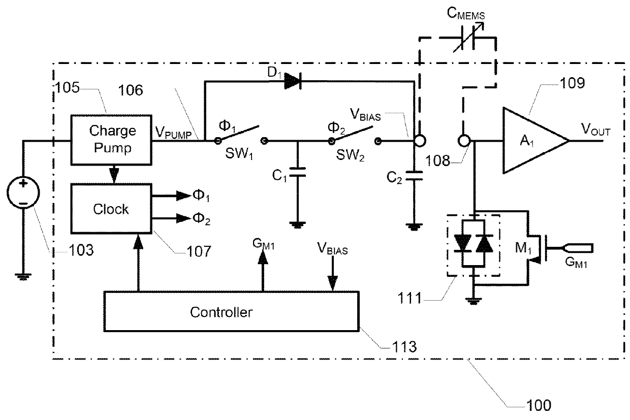
[0040]FIG. 1 is a simplified schematic circuit diagram of a DC bias voltage circuit 100 according to a first embodiment of the invention. The DC bias voltage circuit 100 is integrated on a semiconductor substrate in the present embodiment and may conveniently be manufactured in a sub-micron CMOS process. The DC bias voltage circuit 100 is electrically coupled to opposing diaphragm and back plate structures of a MEMS condenser microphone CMEMS through a pair of pads arranged on the surface of the semiconductor substrate. The MEMS condenser microphone CMEMS is schematically depicted as a variable capacitor illustrating its change of capacitance in response to impinging sound.

[0041]The DC bias voltage circuit 100 receives input power and voltage from an external power supply source 103. This external power supply source 103 may be a DC supply rail of a portable communication device such as a mobile phone. The external power supply source 103 may provide a DC voltage between 1.5 V and 2...


PUM


Abstract

The present invention relates to a DC bias voltage circuit comprising a DC bias voltage generator adapted to supply a first DC voltage. A low-pass filter has an input operatively coupled to the first DC voltage to produce a second DC voltage at a low-pass filter output. The low-pass filter comprises an adjustable switched capacitor resistor setting a cut-off frequency of the low-pass filter and a controller is adapted to controlling a resistance of the adjustable switched capacitor resistor.

Description

BACKGROUND OF THE INVENTION[0001]DC bias voltage circuits are well-known and utilized in a variety of applications to supply a desired DC voltage to an electronic circuit or to a transducer such as a capacitive microphone. In many of these applications, the desired DC voltage is required to possess a very low noise level to prevent that noise from being injected into signals generated by the electronic circuit or the transducer. The noise of the DC bias voltage circuit can include thermal noise and / or voltage ripple or clock signal residues of a DC-DC converter or charge pump forming part of the DC bias voltage circuit. DC-DC converters or charge pumps are often required to generate an appropriate electrical DC bias voltage to a capacitive transducer from a power supply source. The DC bias voltage is required in order to appropriately convert audible sound, or infrasonic or ultra-sonic sound, into a corresponding electrical signal. In particular, in order to guarantee a level of per...

Claims


Application Information

Patent Timeline
Patent Type & Authority Patents(United States)
IPC IPC(8): H04B15/00H02M3/07H02M1/12H04R3/00H04R19/00
CPCH02M3/07H02M1/12H04R3/007H04R19/005H04R2410/03
Inventor JOSEFSSON, OLAFUR MAR
Owner INVENSENSE
Why Eureka
Try Eureka