
System and method for producing modular photovoltaic panel assemblies for space solar arrays

a solar array and solar array technology, applied in the field of photovoltaic arrays and methods of manufacturing photovoltaic arrays, can solve the problems of kawam not disclosing any automated device for the assembly of strings he discloses, damage to 5% to 8% of solar cells, and high cost and cycle time, and achieves high quality and performance. high

Active Publication Date: 2016-09-13
DEPLOYABLE SPACE SYST
View PDF41 Cites 22 Cited by
  • Summary
  • Abstract
  • Description
  • Claims
  • Application Information

AI Technical Summary

Benefits of technology

The present invention is an automated system and method for making and testing interconnected photovoltaic devices. This system can make high-quality photovoltaic panels at a lower cost than existing devices. The system can produce standard power modules for assembly onto a flexible blanket for use in a space solar array. The invention can make both rolled and z-folded configurations. The technical effect of this invention is the ability to make efficient and reliable photovoltaic panels at a low cost, which can be used for space solar power generation.

Problems solved by technology

Kawaam notes this manufacturing process involves the handling of the solar cells during at least four separate operations, which results in excessive cost and cycle time.
He further notes that the process permits only portions of the assembly to be automated and that this process results in damage to 5% to 8% of the solar cells.
However, Kawam does not disclose any automated device for the assembly of the strings he discloses.
Thus, while there have been some efforts to automate the process, there is not a known system or method which provides for the assembly of an SPM suitable for a space solar array by a single automated device.

Method used


Image

  • System and method for producing modular photovoltaic panel assemblies for space solar arrays
  • System and method for producing modular photovoltaic panel assemblies for space solar arrays
  • System and method for producing modular photovoltaic panel assemblies for space solar arrays

Examples


Embodiment Construction

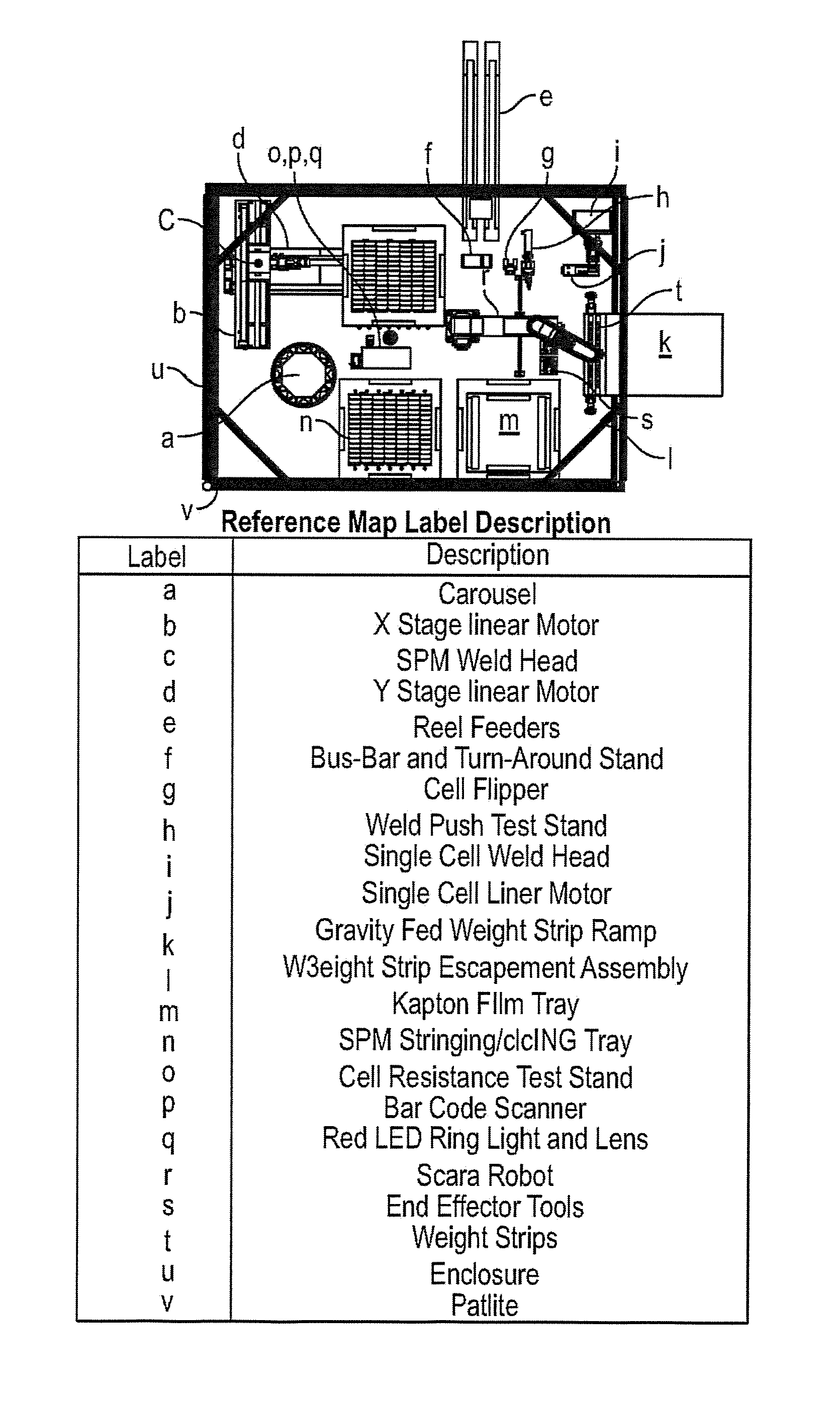
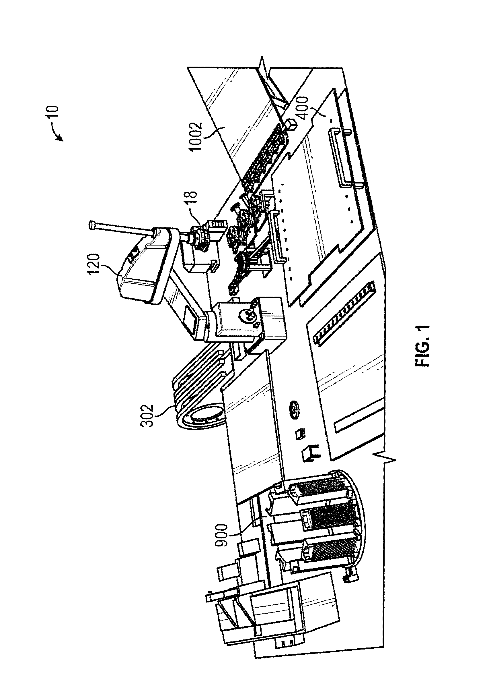
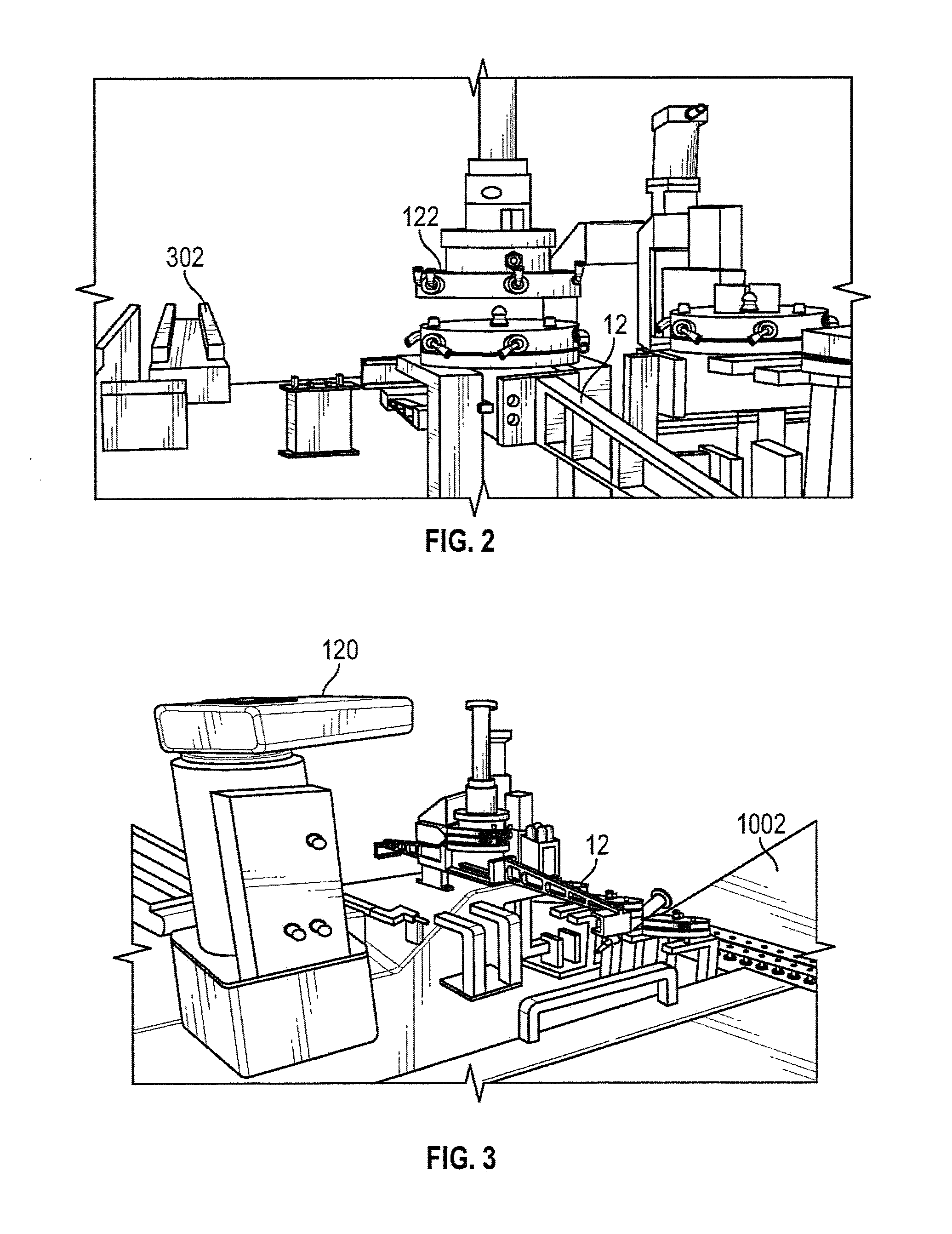
[0046]Referring now to the Figures, an embodiment of the manufacturing device 10 is depicted in FIGS. 1-27 in the process of fabricating an SPM 500, shown as completed in FIG. 27. FIGS. 28-29 show, respectively, a perspective view and a plan view of an embodiment of the assembly work station showing the major subassemblies. FIGS. 30-41 show close-up views of some of the components of the subassemblies. FIG. 42 shows an embodiment of a flipping assembly, used external to the work station, for turning over an SPM which is in the process of being completed. FIGS. 43-45 show flow charts for assembling SPMs from, respectively, CIC's, bare cells, and IMM ICs.

[0047]The manufacturing device 10 is configured to process both standard ZTJ / XTJ PV and emerging IMM PV. The manufacturing device 10 is also designed to manufacture interconnected cells (CIC's), and fully CIC'd cells (glassed) during periods of SPM fabrication downtime. The manufacturing device (also referred to herein as “work statio...


PUM

PropertyMeasurementUnit
translucentaaaaaaaaaa
adhesionaaaaaaaaaa
adhesiveaaaaaaaaaa

Abstract

An automated system provides automated manufacturing of photovoltaic standard power modules for utilization in a space solar array, in both rolled blanket and z-folded configurations. The automated system provides robotically controlled systems for CIC-ing, glassing, stringing, laydown and acceptance testing of interconnected photovoltaic devices. A method of manufacturing the photovoltaic standard power modules includes the steps of robotic positioning of diodes, interconnects and busbars onto a SPM stringing tray followed by the robotic positioning of bare cells into position adjacent to the diodes, interconnects and busbars to form strings. The SPM stringing tray is thereafter robotically positioned adjacent to an integral welder for welding of the front side of the string. Cover glass is thereafter robotically placed over the cells. The string is flipped and the backside of the string is robotically positioned for welding.

Description

RELATED APPLICATIONS[0001]U.S. Application No. 61 / 988,102 for this invention was filed on May 2, 2014 which application these inventors claim domestic priority, and which application is incorporated in its entirety.BACKGROUND OF THE INVENTION[0002]The present invention relates to photovoltaic arrays and methods of manufacturing photovoltaic arrays. More particularly, the present invention relates to a method and a system for the manufacture of power modules for solar arrays that require less time and labor than required for presently known methods and systems. Various space craft and man-made satellites utilize photovoltaic (“PV”) arrays for recharging of batteries and / or operation of various systems. The PV arrays are a collection of solar cells formed into a unit referred to as a “CIC” (solar cell-interconnect-coverglass). The completed CICs are assembled into strings which are configured into standard power modules (SPMs). The SPMs include interconnected solar cell assemblies, fr...

Claims


Application Information

Patent Timeline
Patent Type & Authority Patents(United States)
IPC IPC(8): B23K37/00H01L31/18H01L31/041
CPCH01L31/18H01L31/041B23K2101/36H01L31/188Y02E10/50B23K9/00Y02P70/50
Inventor SPENCE, BRIAN RWHITE, STEPHEN FALLMANDINGER, TIFFANY NCRONIN, PAUL
Owner DEPLOYABLE SPACE SYST
Learn More