
Power management architecture based on microprocessor architecture with embedded and external non-volatile memory

a microprocessor and microprocessor technology, applied in the direction of memory adressing/allocation/relocation, instruments, liquid/fluent solid measurement, etc., can solve the problems of inability to implement a re-writable non-volatile memory, inability to meet the needs of customers-users, and significant cost of large ram usage, etc., to achieve the effect of strengthening protection

Active Publication Date: 2016-09-27
STMICROELECTRONICS INT NV
View PDF20 Cites 3 Cited by
  • Summary
  • Abstract
  • Description
  • Claims
  • Application Information

AI Technical Summary

Benefits of technology

This patent describes a microprocessor architecture that offers flexibility and reduced design risks. It also allows for the creation of a dedicated logic block using a fast, re-writable non-volatile memory (NVM) external to the PMU device. The design can be customized entirely with a customer-user design, and may optionally contemplate data cryptation. An encryption algorithm can greatly enhance protection. It can be implemented in ROM and enabled or disable, and the presence of the algorithm may or may not be publicized by the manufacturer of the integrated device.

Problems solved by technology

Nevertheless, Server developers, which on one hand have participated in the definition of the standard, may consider a core set of commands and functions indispensable but not sufficient to their own specifications and therefore the developers may add to the list of commands or to the PMBUS.org standard, specific proprietary additional commands of their systems and know-how.
However, by cost concern, conventional PMU CMOS fabrication processes do not offer the possibility of implementing a re-writable nonvolatile memory (EEPROM or FLASH) for containing data for executing the commands.
The example technique offers economic advantages by avoiding the need of a very large RAM, which is often not acceptable by the customer-user.
Furthermore, in mixed signal silicon technology, the usage of large RAM is a relevant cost.

Method used


Image

  • Power management architecture based on microprocessor architecture with embedded and external non-volatile memory
  • Power management architecture based on microprocessor architecture with embedded and external non-volatile memory
  • Power management architecture based on microprocessor architecture with embedded and external non-volatile memory

Examples


example

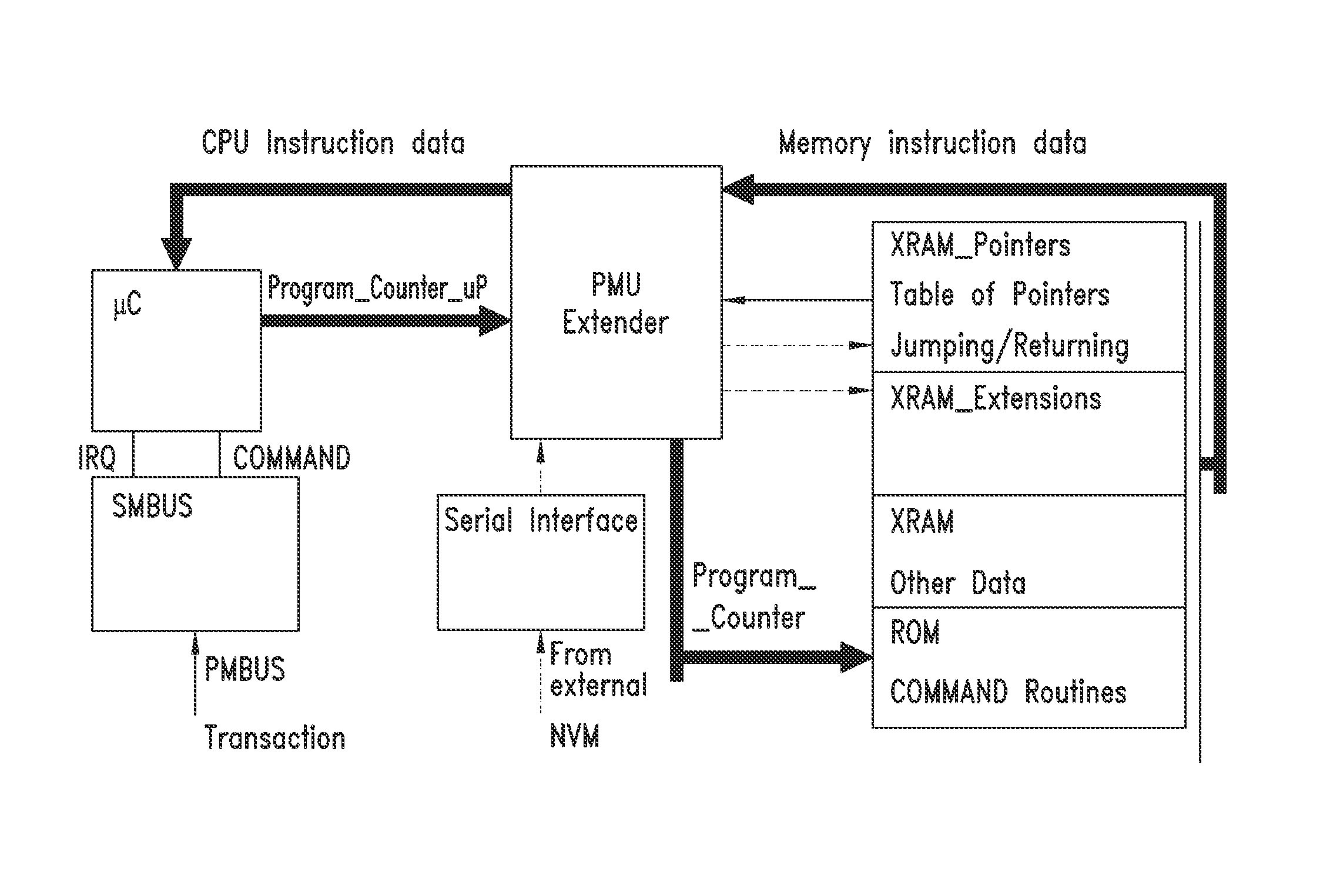
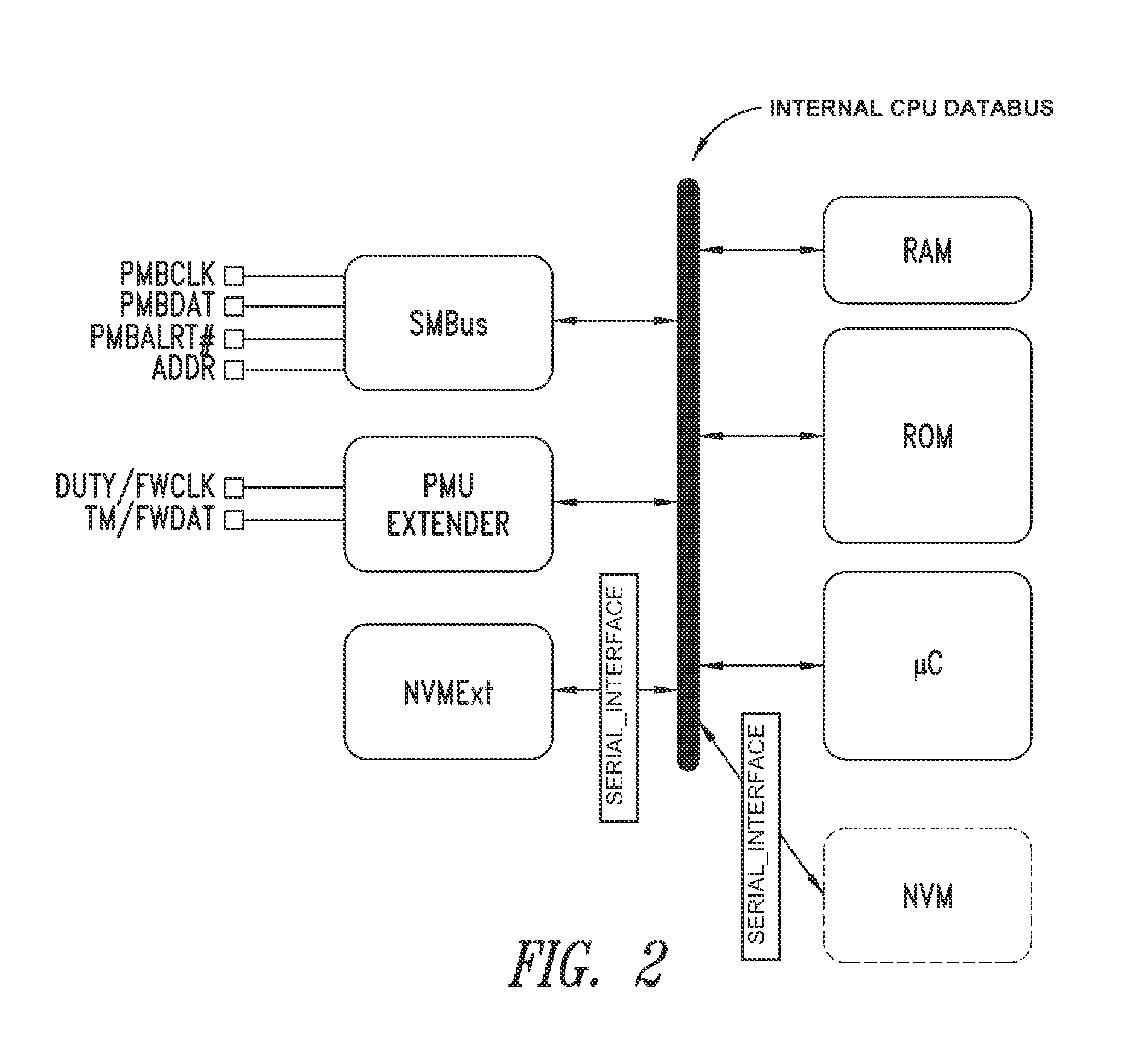
[0042]With reference to the schema of a possible embodiment of FIG. 4, at start-up, the logic function of the block PMU_EXTENDER is enabled. An exemplary basic circuit in FIG. 5 depicts a scheme through which two tables are serially downloaded from an external memory NVMext. The serial path, together with data from the external memory which is translated in bytes, fills the pointer table XRAM_Pointers and the extension table XRAM_Extensions in a predetermined order. The extension table XRAM_Extensions represents the program code written by the custom-user which is executed for correcting or extending the PMBUS commands towards the respective POL.

[0043]Downloading of data from the external memory NVMext maybe subject to an integrity check of data (parity bit, sum check) and to encryption.

[0044]The data of the tables are optionally released after integrity control and decrypting have been tested. The data stream at start-up is indicated with a hatched line in the schema of FIG. 4.

[004...


PUM


Abstract

A control unit for power supply circuits of points of load (POL) of an electronic system includes a means for autonomous customization by the customer-user of the original control program residing in the ROM of the device, as well as configuration of control parameters of the POL. Microprocessor architecture of the device includes a dedicated logic block and a rewritable non-volatile memory coupled to the data bus of the device or to an auxiliary bus thereof, thus providing a means for software extension of the power supply circuits. RAM is loaded at start-up with data of modified or added routines for implementing new commands and values of configuration and control data of the POL. The RAM may optionally be subjected to encryption / decryption for protection. During operation, program execution jumps from ROM address space to RAM address space and vice versa when certain values of a program counter are reached.

Description

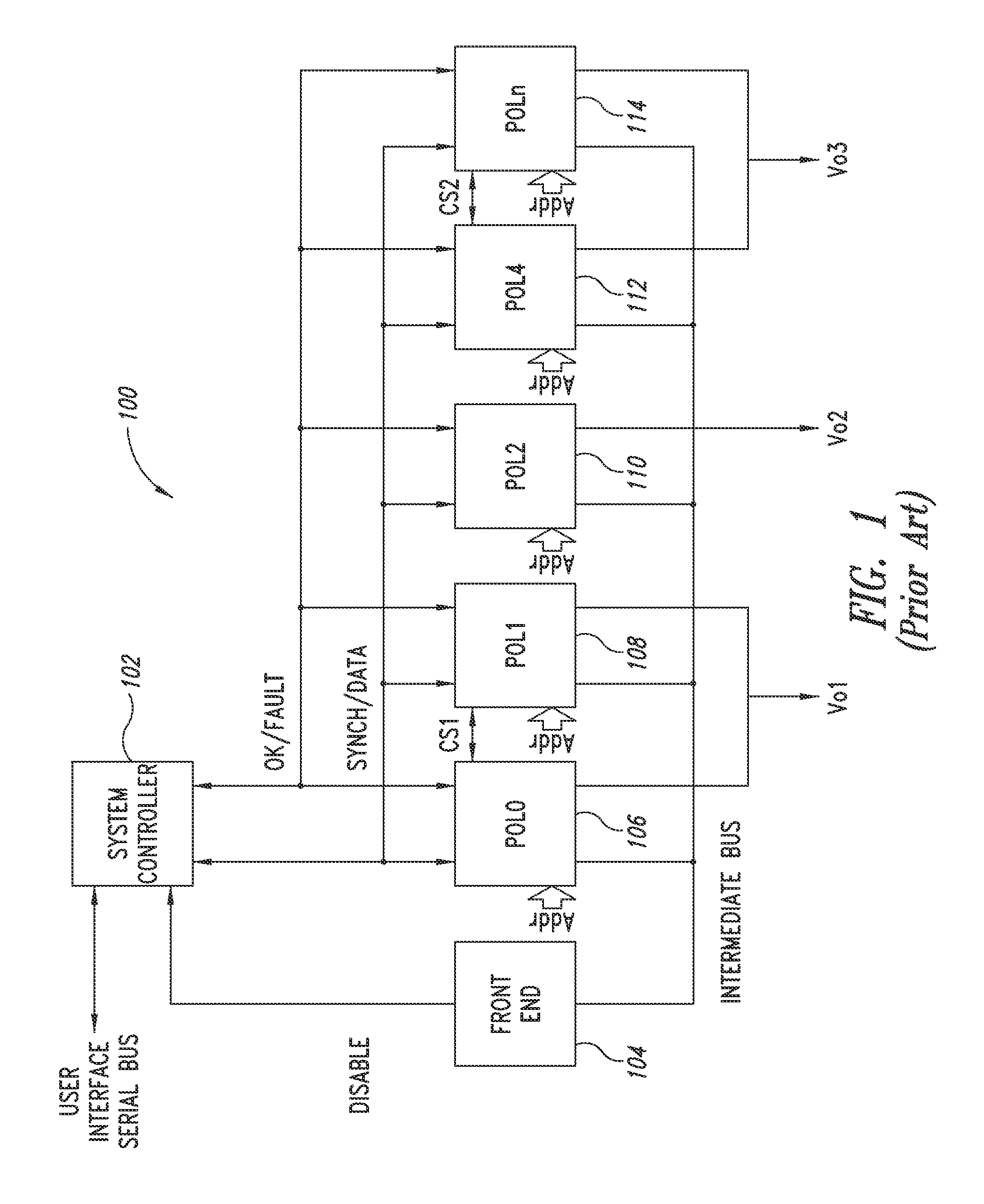
BACKGROUND[0001]1. Technical Field[0002]The present disclosure relates in general to control systems of the power supply of complex electronic systems and in particular to a method of controlling a plurality of voltage regulators for as many load points of the system.[0003]2. Description of the Related Art[0004]A digital system for managing the power supply of complex electronic systems, briefly a PMU, acronym for Power Management Unit, is a digital unit adapted to manage programming, control, and telemetry of numerous voltage regulators deployed as load points of the electronic system (briefly POL, acronym for Point Of Load) associated thereto. Each voltage regulator or POL may include a serial digital interface, at least one synchronizing signal, a clock signal, a data transfer signal, and data signals to the PMU for accomplishing its tasks.[0005]Implementation of the PMU consists today in a description of commands (COMMAND) customized to a specific POL that is identified with an ...

Claims


Application Information

Patent Timeline
Patent Type & Authority Patents(United States)
IPC IPC(8): G06F1/32G06F1/26H02J1/08G06F12/02G06F12/12
CPCG06F1/3275G06F1/26G06F1/32G06F12/0246H02J1/08G06F12/12
Inventor ZAFARANA, ALESSANDRO
Owner STMICROELECTRONICS INT NV
Learn More