Electron beam gun with kinematic coupling for high power RF vacuum devices

a vacuum device and electron beam technology, applied in the direction of electron/ion guns, electron/ion guns transit tubes, cathode ray tubes/electron beam tubes, etc., can solve the problems of reducing the efficiency of electron guns. , to achieve the effect of high mechanical stiffness, repeatable alignment and use in machining operations

Active Publication Date: 2016-11-22
DYMENSO LLC
View PDF11 Cites 4 Cited by
  • Summary
  • Abstract
  • Description
  • Claims
  • Application Information

AI Technical Summary

Benefits of technology

[0011]In one aspect, the present invention provides an electron beam device whose components are precisely aligned and joined using a kinematic coupling. The kinematic coupling creates a deterministic interface having six points of contact between the mating components, which fully constrains the respective orientation of the mating components. Convex coupling elements are fabricated to withstand concentrated Hertzian contact stresses in high temperature applications. The coupling elements are individually joined to the first mating component in a manner which is compatible with ultra-high vacuum environments and which enables repeatable alignment and use in machining operations through high mechanical stiffness. Machining of mating components in the final assembly position ensures precise alignment in an electron beam device.

Problems solved by technology

However, kovar is magnetic, making it not suitable for use in electron guns.
Also, these thermally expansion matched metals only work to a braze temperature of about 800 degrees, above that the thermal expansion between ceramics and the base metal starts to diverge and the stresses tend to become too high.

Method used


Image

  • Electron beam gun with kinematic coupling for high power RF vacuum devices
  • Electron beam gun with kinematic coupling for high power RF vacuum devices
  • Electron beam gun with kinematic coupling for high power RF vacuum devices

Examples


Embodiment Construction

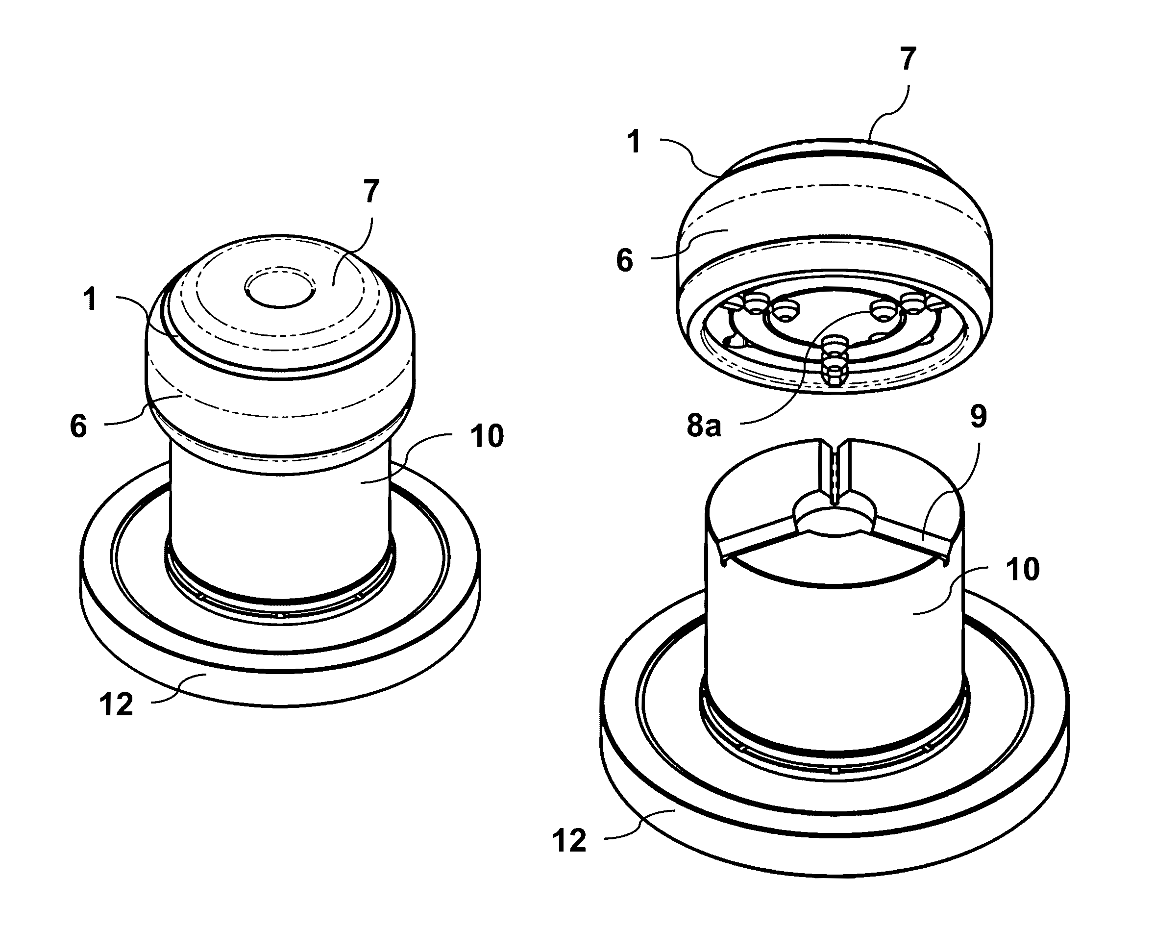
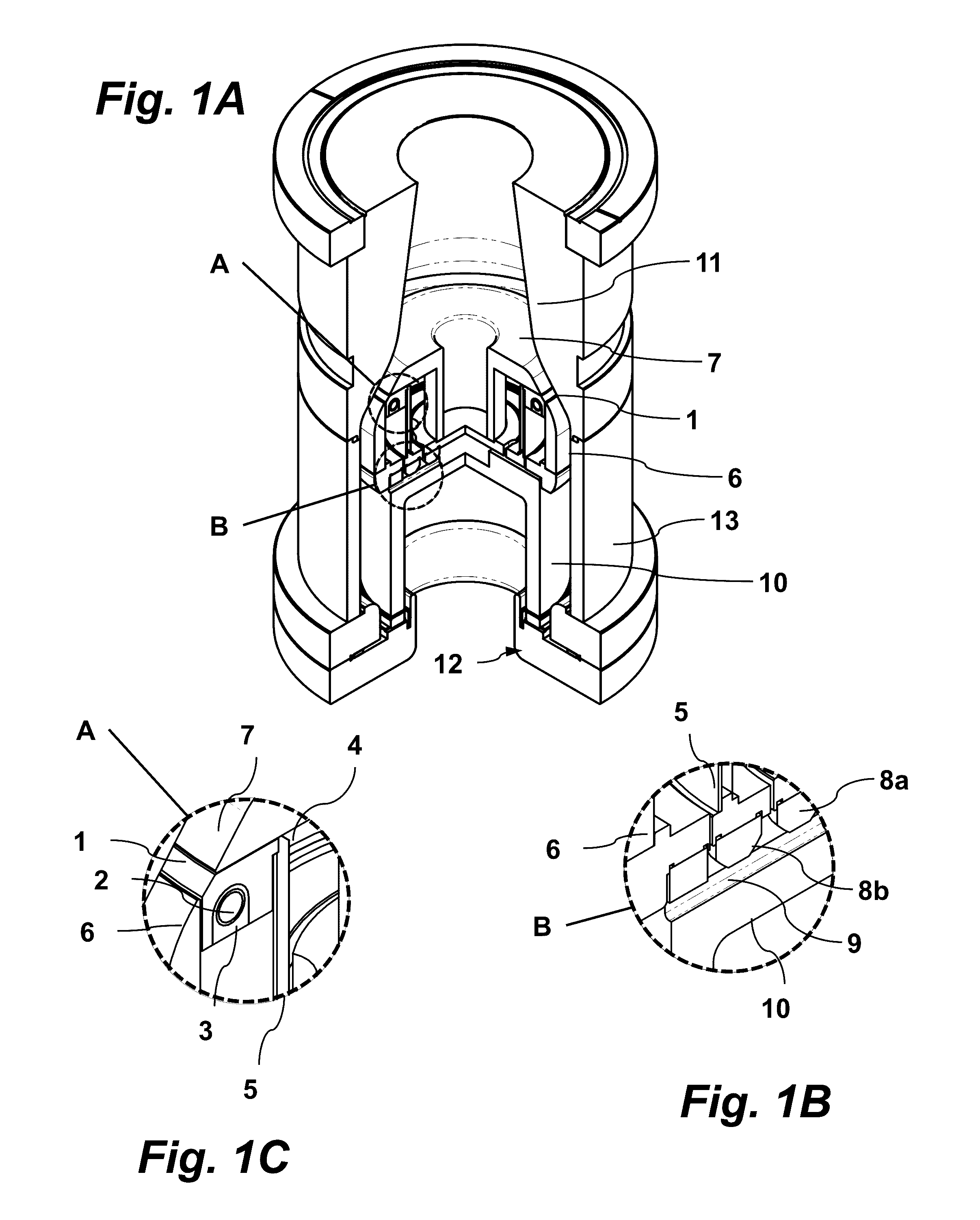
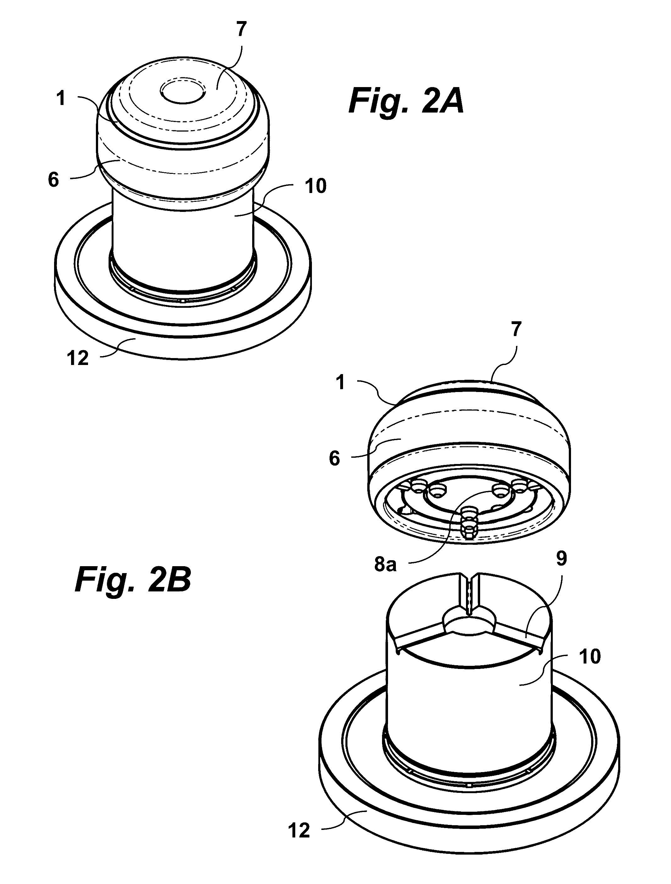
[0032]Electron beam devices according to embodiments of the present invention feature kinematic couplings, e.g., with a ball-in-groove joint where three balls on one component mate with three grooves on the second component with small area contacts. The kinematic couplings are deterministic: They only make contact at a number of points equal to the number of degrees of freedom that are to be restrained. Being deterministic makes performance predictable and also helps to reduce design and manufacturing costs. Kinematic couplings have traditionally been used in instrument design where the loads typically are relatively light and static. Through the use of well-engineered contact areas and / or advanced ceramic materials they are can be made quite robust and suitable for demanding applications requiring high stiffness and load capacity.

[0033]FIGS. 1A-C are cut-away perspective views of an electron beam gun for a high power RF vacuum device according to an embodiment of the invention. As ...


PUM

PropertyMeasurementUnit
elastic modulusaaaaaaaaaa
flexural strengthaaaaaaaaaa
operating voltagesaaaaaaaaaa

Abstract

An electron beam gun for a high power RF vacuum device has components joined by a fixed kinematic coupling to provide both precise alignment and high voltage electrical insulation of the components. The kinematic coupling has high strength ceramic elements directly bonded to one or more non-ductile rigid metal components using a high temperature active metal brazing alloy. The ceramic elements have a convex surface that mates with concave grooves in another one of the components. The kinematic coupling, for example, may join a cathode assembly and/or a beam shaping focus electrode to a gun stem, which is preferably composed of ceramic. The electron beam gun may be part of a high power RF vacuum device such as, for example, a gyrotron, klystron, or magnetron.

Description

STATEMENT OF GOVERNMENT SPONSORED SUPPORT[0001]This invention was made with Government support under Contract No. DE-SC0009599 awarded by the Department of Energy. The Government has certain rights in the invention.FIELD OF THE INVENTION[0002]The present invention relates to high power RF vacuum devices. More specifically, it relates to high power electron beam guns designed for alignment with high precision and the ability to withstand high temperature conditions.BACKGROUND OF THE INVENTION[0003]An electron beam gun, or emitter, is an electrical component used in a wide variety of vacuum devices. Low power electron beam guns, for example, are commonly used in cathode ray tube (CRT) displays. High power electron beam guns are used in microwave linear beam vacuum devices such as klystrons and gyrotrons, which have applications to particle accelerators and nuclear fusion reactors. For example, the International Thermonuclear Experimental Reactor (ITER) tokamak has an electron cyclotro...

Claims


Application Information

Patent Timeline
Patent Type & Authority Patents(United States)
IPC IPC(8): H01J23/06H01J29/04H01J29/48H01J29/58
CPCH01J23/06H01J29/04H01J29/485H01J29/58H01J2223/06H01J2223/08H01J2229/481H01J2229/4831H01J25/02H01J23/07
Inventor BORCHARD, PHILIPP
Owner DYMENSO LLC
Why Eureka
Try Eureka