

Antipodal vivaldi antenna array for biomedical imaging
- Summary
- Abstract
- Description
- Claims
- Application Information
AI Technical Summary
Benefits of technology
Problems solved by technology
Method used
Image

Examples
Embodiment Construction
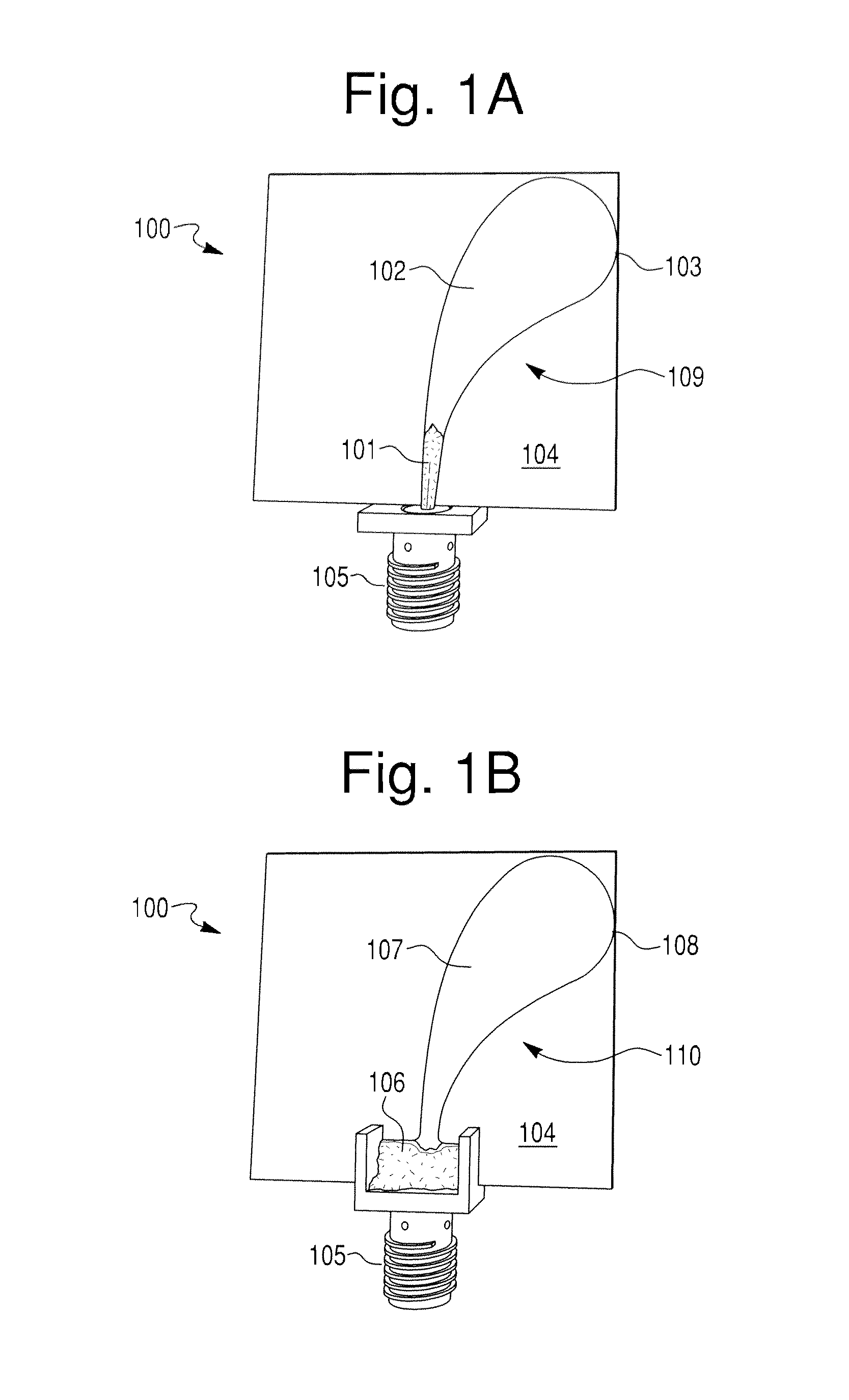
[0028]FIG. 1A shows the front side of one embodiment of the present antipodal Vivaldi antenna 100. The front side lobe 109 comprises a circularly tapered end 103 that preferably takes on a tilted half disc shape. This preferred tilted half disc shape is shown in greater detail in FIG. 8. The front side lobe 109 transitions from the circularly tapered end 103 to an exponential structure 102 wherein the width of the lobe 109 narrows exponentially to the bottom of the structure 102 The front side lobe 109 then transitions to a microstrip 101. The microstrip 101 is connected to a coupling device 105 that connects the microstrip 101 to the source feeds from the microwave imaging system, shown in FIG. 13. The coupling device 105 is preferably a SMA connector. The front side lobe 109 is placed on the front side of a substrate 104. The substrate 104 is preferably constructed using TMM 10 from the Rogers Corporation, and has a thickness of 1.27 mm, and a relative permittivity of 9.2.
[0029]FI...
PUM
 Abstract
Description
Claims
Application Information