Method for manufacturing fuel cell separator
a technology of fuel cell separator and manufacturing method, which is applied in the direction of final product manufacturing, sustainable manufacturing/processing, liquid/solution decomposition chemical coating, etc., can solve the problems of unintentional increase of contact resistance, so as to suppress an increase in contact resistance and improve the corrosion resistance of the separator , the effect of increasing the outpu
- Summary
- Abstract
- Description
- Claims
- Application Information
AI Technical Summary
Benefits of technology
Problems solved by technology
Method used
Image

Examples
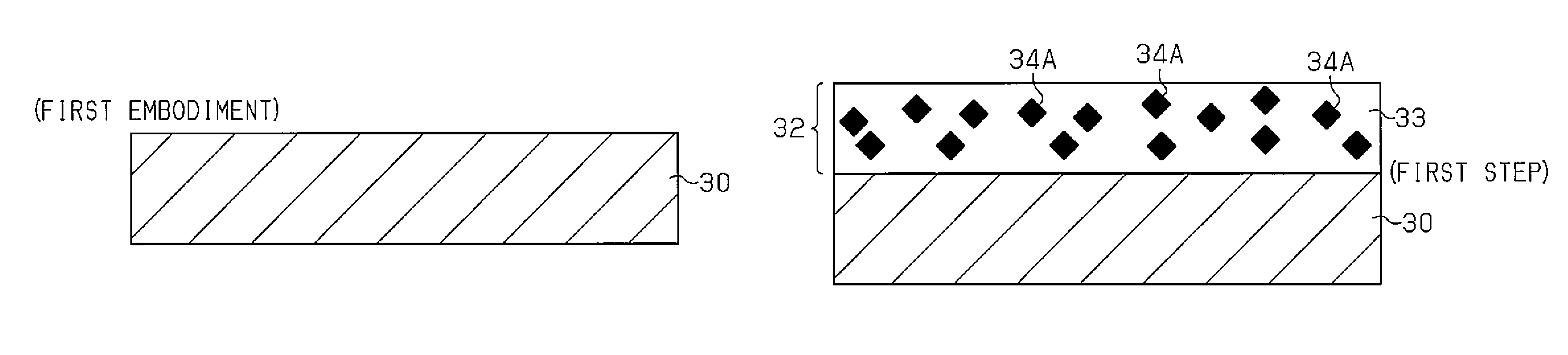
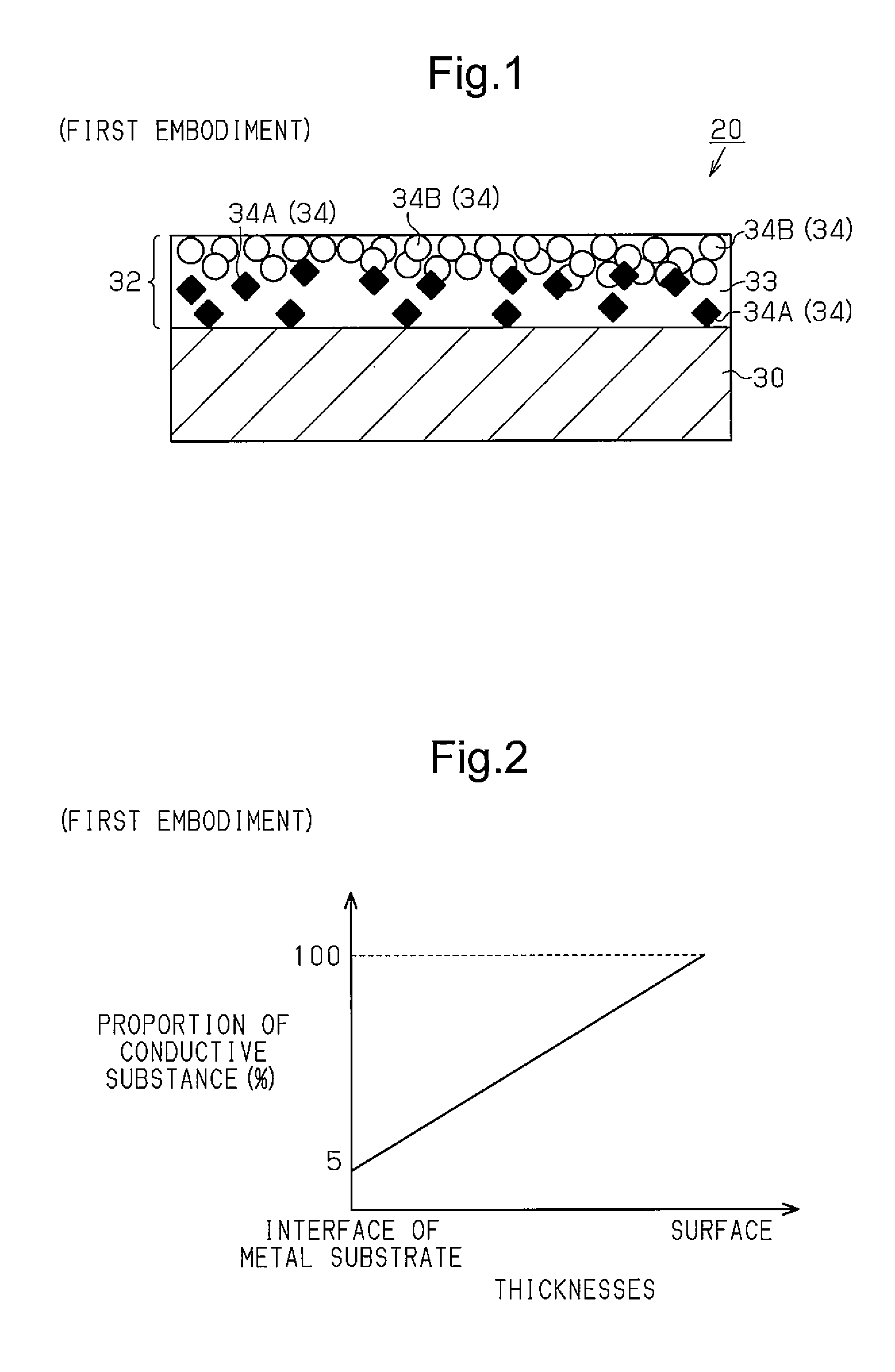
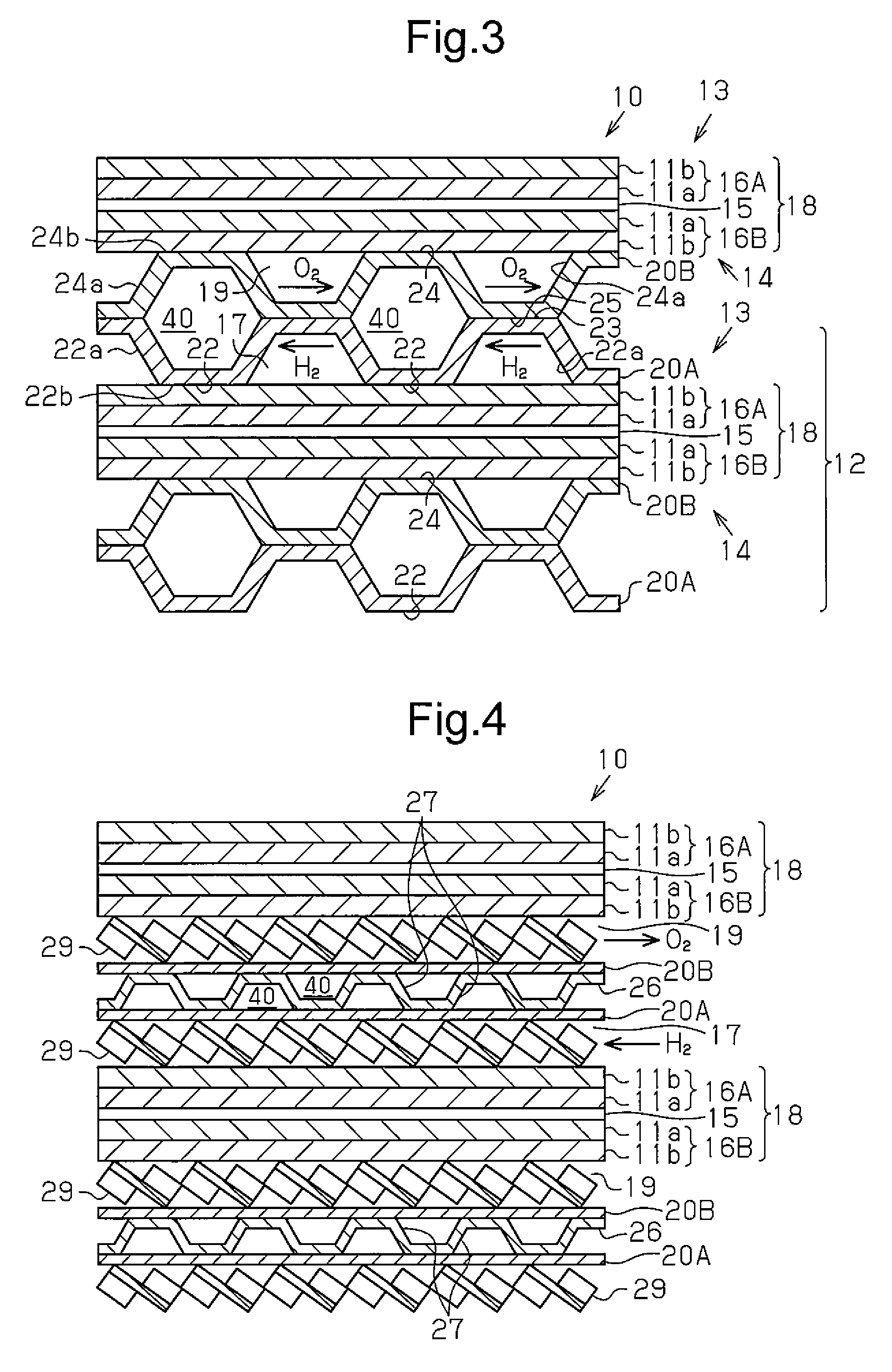
first embodiment
Operation of First Embodiment
[0115]When the thus-configured separator 20 is used in the fuel cell 10 in the first example of the configuration shown in FIG. 3 and the fuel cell 10 in the second example of the configuration shown in FIG. 4, the surface of the separator contacting the gas diffusion layer (GDL) 11b can sufficiently ensure a conductive path. The proportion of the conductive substance in the conductive resin layer 32 continuously increases from the interface of the metal substrate toward the surface of the separator 20. This configuration prevents an increase in the interface resistance at the interface between the portion having the first conductive substance 34A and the portion having the second conductive substance 34B mainly, and also reduces the specific resistance. For this reason, the contact resistance between the separator 20 and other members (GDL, another separator) is significantly reduced. This configuration can sufficiently ensure the conductive path on the...
second embodiment
[0123]Next, a separator according to a second embodiment will be described with reference to FIG. 6.
[0124]For the purposes of illustration, the same reference numerals will be given to the same or corresponding components as those in the first embodiment.
[0125]As shown in FIG. 6D, in the separator 20 according to the second embodiment, a metal substrate 30 has the same configuration as that in the separator according to the first embodiment. For the purposes of illustration, the separator 20 is illustrated as a flat plate in FIG. 6. The separator 20 used in First example of the configuration of the fuel cell has projections 22 to 25. For the purposes of illustration, the ratio of the thickness of the metal substrate 30 to the thickness of the conductive resin layers 32A and 32B shown in FIG. 6 is different from the actual ratio.
[0126]As shown in FIG. 6D, on at least one surface of the metal substrate 30 (one surface for an end metal substrate 30 of the stack structure), a first cond...
third embodiment
Operation of Third Embodiment
[0173]The thus-configured separator 20 has the same operation as that of the first embodiment and the following action.
[0174]In the first embodiment, if the resin is pressurized with a pressing means (such as a hot press and a cold press above) before the resin is cured, an uncured resin in the conductive resin main layer 32 is forced into gaps between particles of the second conductive substance 34B, and is cured. At this time, the resin in contact with the surface of the metal substrate 30 may move toward the surface of the separator to cause defects. When such a separator is used in the fuel cell, metal ions in the metal substrate 30 may elute to the defected sites to reduce corrosion resistance. In contrast, in the third embodiment, when the resin 33 contained in the conductive resin main layer 32 is pressurized by a pressing means, the sublayer resin in the conductive resin sublayer 42 is already cured, and the resin in contact with the metal substr...
PUM
| Property | Measurement | Unit |
|---|---|---|
| thickness | aaaaa | aaaaa |
| length | aaaaa | aaaaa |
| length | aaaaa | aaaaa |
Abstract
Description
Claims
Application Information
 - R&D
- Intellectual Property
- Life Sciences
- Materials
- Tech Scout
- Unparalleled Data Quality
- Higher Quality Content
- 60% Fewer Hallucinations
Browse by: Latest US Patents, China's latest patents, Technical Efficacy Thesaurus, Application Domain, Technology Topic, Popular Technical Reports.
© 2025 PatSnap. All rights reserved.Legal|Privacy policy|Modern Slavery Act Transparency Statement|Sitemap|About US| Contact US: help@patsnap.com