
Constrained interleaving for 5G wireless and optical transport networks

a wireless and optical transport network, constrained technology, applied in the direction of coding, error correction/detection using convolutional codes, error correction/detection using turbo codes, etc., can solve the problems of high data rate, high hardware complexity of 4g lte ctc, etc., to increase the performance and data rate of the optical communication system

Inactive Publication Date: 2017-02-07
FONSEKA JOHN P +1
View PDF36 Cites 17 Cited by
  • Summary
  • Abstract
  • Description
  • Claims
  • Application Information

AI Technical Summary

Benefits of technology

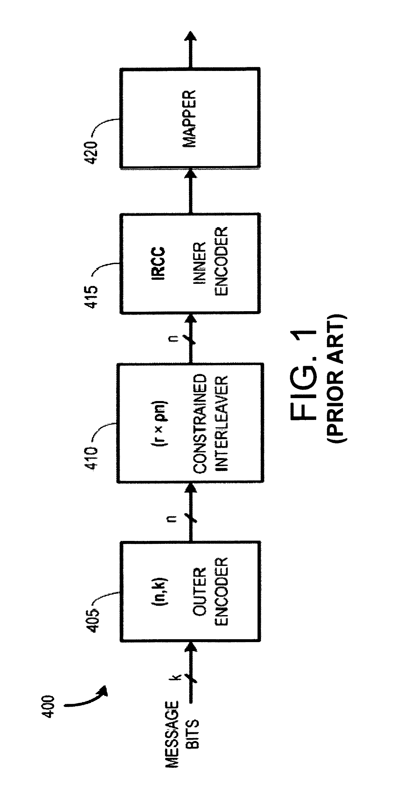
[0040]In accordance with a first aspect of the present invention, constrained interleavers are designed that only use a single row vector as opposed to CI-1 or a CI-2 design matrix which always needs more than one row to meet non-trivial MHD design objectives. For example, CI-3 and CI-4 constrained interleavers are designed by identifying restricted zones of numbers where a pseudo-random number generator cannot generate an output. These restricted zones correspond to sets of adjacent integers within the integer domain [0,K-1]. The length of the constrained interleaver is K, and is used to permute the integer ring [0,K-1]=[0, . . . ,K-1] to a permuted version of this integer ring, which can be denoted as π[0,K-1]. An unconstrained pseudo-random permutation can map [0,K-1] to any reordering of [0,K-1]. In contrast, a constrained interleaver in accordance with the present invention imposes constraints that eliminate any possible reordering that would cause a particular index of [0,K-1] to be mapped to a position (index) in π[0,K-1] that would violate a constraint. The constraints are implemented by sequentially pseudo-randomly permuting (placing) indices (positions) in the integer ring [0,K-1] to new positions (indices) in π[0,K-1] subject to the constraint of not permuting any index of [0,K-1] into any restricted zone in π[0,K-1]. The restricted zones are used to identify ranges of indices in π[0,K-1] where, if a particular index from [0,K-1] were to be placed, a low weight a CTBC codeword would be / could be generated. Herein, the phrases “low weight codeword,”“low weight error sequence,” and “low distance error sequence” generally correspond to any possible low weight encoded bit sequences, iP, of weights dt≦d≦df where none of the possible low weight encoded bit sequences, iP, can have a weight less than dt. Here the weights dt≦d≦df correspond to Hamming distances, and the coded sequence can be a CTBC coded sequence or some other kind of encoded sequence encoded in accordance with a code for which the low weight error sequences can be identified and enumerated. The interleaver constraints are used to eliminate the possibility of the generation / existence of any low weight CTBC codewords that have weight below a target MHD value denoted as dt.
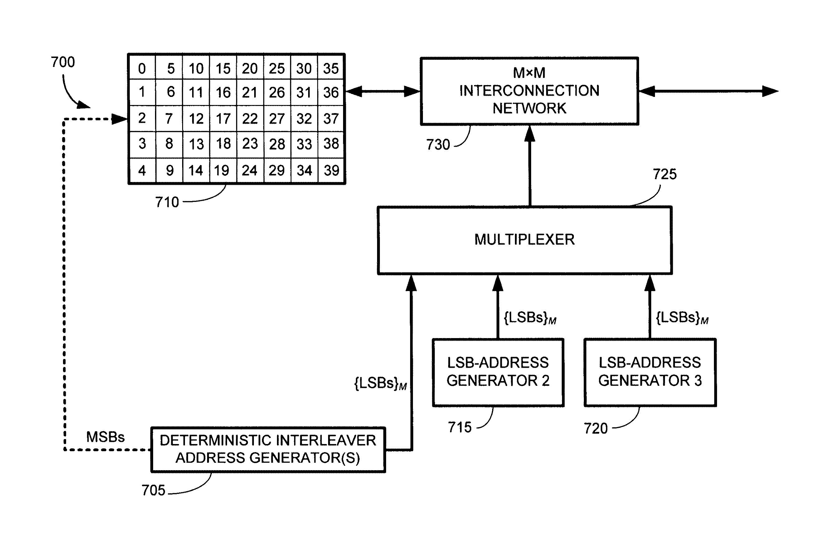
[0042]SRCI as performed in accordance with the present invention provides several advantages. First, the interleaver gain can be improved in comparison to the prior art CI-2 because the number of restricted-out permutation possibilities decreases with respect to the CI-2 design method. Second, it is possible to design CTBC codes that allow different target MHD values to be used for different categories of low weight error sequences. This is important because certain categories of low distance error sequences can be identified that are relatively much less likely. These categories of low distance error sequences have low associated error coefficients. Therefore, the overall probability of error can be reduced by allowing lower MHD to these less likely categories of low distance error sequences. This allows the overall probability of error to be reduced by balancing MHD and error coefficient products in the error probability expression as a function of distance spectra. A third advantage to the SRCI approach is that it provides additional flexibility that allows vectorizable (contention free) deterministic constrained interleavers to be designed using the single row type interleaver constraints.
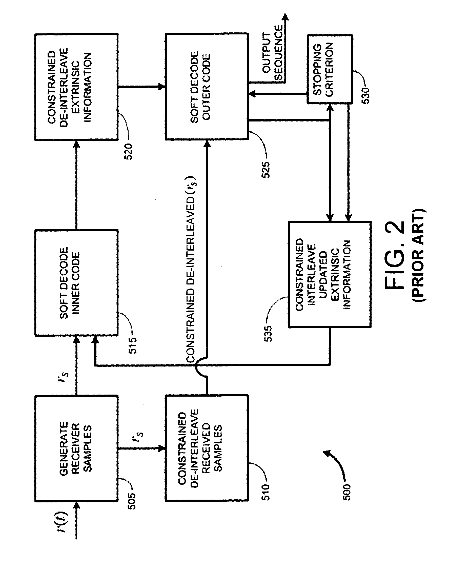
[0044]Another aspect of the present invention centers around CICM (constrained interleaved coded modulation). CICM signal mapping is used to map coded sequences such as CTBC coded sequences and other coded sequences for which the low distance error sequences (lowest weight codewords) can be identified and tabulated. CICM signal mappers uses a permutation, Γ, to permute the coded bit positions of a coded bit stream of frame of frame size K, onto a sequence of K / m groups of m bits, each of which will be mapped to an 2m-ary symbol in accordance with a selected constellation mapping rule. The constellation mapping rule is preferably uses RGC (reverse Gray coding) to map groups of m bits at a time onto the 2m-ary signal constellation points. The combination of the CICM permutation Γ and the constellation mapping rule is preferably designed to ensure that at least one of a symbol Hamming distance and a MSED (minimum squared Euclidian distance) is achieved. This is achieved by keeping track of a set of low distance error sequences that can be generated at weights d, where dt≦d≦df. Similar to the CI permutation π[0,K-1], Γ is constrained to ensure that low distance error sequences are avoided, but now in terms of symbol Hamming distance and MSED on the transmitted sequence as opposed to the encoded bit stream itself. In preferred embodiments both the symbol Hamming distance and the MSED are jointly achieved. In unequal error protection embodiments, the symbol Hamming distance and a plurality of different MSEDs for different subsets of message bits are jointly achieved. In all such systems mentioned above, when AWGN (additive white Gaussian noise) channels are in use, it may not be needed to maintain a given symbol Hamming distance, so that the maintaining / achieving a given symbol Hamming distance portion becomes optional. In general, the CICM permutation and mapping is selected to improve or optimize the net probability of error on the channel.
[0046]Another aspect of the present invention involves the design of OTN (optical transport network) systems for 100G and beyond fiber optic or free space laser communication systems. The present invention shows how to design and implement optical subsystems using filter banks constructed using a plurality of known optical discrete-time filters that can be implemented in coupled fiber subsystems and / or optical integrated circuits. The optical discrete time filter banks are used to implement a transmit portion of a MIMO type channel matrix, H. The output of the optical discrete time filter banks is coupled onto a single fiber or free space optical laser channel for transmission. At the receiver, another optical filter bank is used to implement a receive portion of the MIMO type channel matrix, H. Both SM and MIMO type modulation formats are disclosed. The SM and MIMO type systems can be used to increase the performance and data rate of the optical communication system at a given noise level.

Problems solved by technology

This CTC leads to very complicated rate matching circuits at both the encoder and the decoder, thus increasing over all hardware complexity of the 4G LTE CTC encoding and decoding.
OTN applications are demanding because they require very high data rates and powerful codes and the frame size used in coding / decoding is long, (122,368 message bits plus coding overhead bits).
OTN applications cannot use CTCs like LTE does because the error floors required by OTN applications are far below those afforded by CTCs.
However, the interleaver gain attainable by the CI-2 is limited to a large extent by the number of rows, L in the CI-2 design matrix.
However, when CI-2 interleavers are used, lowering L will eventually limit the achievable MHD.
The construction of the CI-2 requires many randomization operations performed in the CI-2 design matrix and a complicated process of ensuring that randomizations do to not violate any constraints in the CI-2 design matrix.
As discussed below, this CI-2 design matrix and design process actually limits BER performance.

Method used


Image

  • Constrained interleaving for 5G wireless and optical transport networks
  • Constrained interleaving for 5G wireless and optical transport networks
  • Constrained interleaving for 5G wireless and optical transport networks

Examples


Embodiment Construction

[0078]Throughout this written description various mathematical algorithms will be presented in the form of block diagrams. It is to be understood that in any such cases, the block diagrams can be viewed as hardware blocks or logic blocks that could be carried out in software. Likewise, especially in hardware implementations, a given block in the any block diagram herein could be embodied using two or more separate hardware sub- blocks. Hence all such modifications are contemplated as ways to implement various aspects and embodiments of the present invention. Also, it should be recognized that any block diagram whose operation is described herein can be viewed as a flow chart, thereby describing a method in addition to a system or an apparatus.

Constrained Interleaver Mathematical Notation

[0079]A single frame of a CTBC code can be modeled starting from a set of ρ independent message blocks, each of length k, mj=(mj1,mj2, . . . mjk), j=0,2, . . . , ρ−1, where ρ is the integer number of...


PUM


Abstract

The present invention provides a design framework that is used to develop new types of constrained turbo block convolutional (CTBC) codes that have higher performance than was previously attainable. The design framework is applied to design both random and deterministic constrained interleavers. Vectorizable deterministic constrained interleavers are developed and used to design parallel architectures for real time SISO decoding of CTBC codes. A new signal mapping technique called constrained interleaved coded modulation (CICM) is also developed. CICM is then used to develop rate matching, spatial modulation, and MIMO modulation subsystems to be used with CTBC codes and other types of codes. By way of example, embodiments are primarily provided for improved 5G LTE and optical transport network (OTN) communication systems.

Description

BACKGROUND OF THE INVENTION[0001]Field of the Invention[0002]The present invention relates generally to methods, apparatus and systems for communication encoders, decoders, transmitters, receivers and infrastructure and / or user devices. More particularly, aspects of the invention relate to constrained turbo block convolutional codes, constrained interleaving, and related methods, apparatus, and systems for improved constrained interleaving, encoding, decoding, signal mapping, MIMO applications, spatial modulation, and rate matching. The present invention also relates to efficient parallel ASICs and VLSI architectures and optical integrated circuit architectures to implement these methods, apparatus, and systems.[0003]Description of the Related Art[0004]A large body prior art includes of technical publications, patents, and standards that relate to 4G LTE (fourth generation long term evolution) wireless systems. In particular, the relevant prior art relates to encoding and decoding a...

Claims


Application Information

Patent Timeline
Patent Type & Authority Patents(United States)
IPC IPC(8): H03M13/00H03M13/27H03M13/29
CPCH03M13/2792H03M13/2906H03M13/036H03M13/05H03M13/23H03M13/2703H03M13/2771H03M13/2972H03M13/258H03M13/1102
Inventor FONSEKA, JOHN PDOWLING, ERIC MORGAN
Owner FONSEKA JOHN P
Learn More