Powder recycling system

a technology of a recycling system and a recycling system, which is applied in the direction of separation process, gas current separation, filtration separation, etc., can solve the problems of long-term exposure to flying dust, labor-intensive three-dimensional object forming apparatus using the conventional rapid prototyping technology, and polluted working environment of dust, etc., to achieve more user-friendly and cost-effective effects

Active Publication Date: 2017-03-07
MICROJET TECH
View PDF14 Cites 9 Cited by
  • Summary
  • Abstract
  • Description
  • Claims
  • Application Information

AI Technical Summary

Benefits of technology

[0009]A first object of the present invention provides a powder recycling system. The components of the powder recycling system are in communication with each other through corresponding ducts so as to form a close-type powder recycling system. Since it is not necessary to install the multi-port valve to switch the airflow path, the powder recycling system is more user-friendly and cost-effective.
[0010]A second object of the present invention provides a powder recycling system for recycling the remaining powder as the construction powder by multiple-steps filtering procedures. After a first filtering procedure is performed by a cyclone separator, about 95% to 99% of the remaining powder is recycled to a powder feeder. After a second filtering procedure is performed, about 1% to 5% of the remaining powder is recycled to the powder feeder. After the third filtering procedure is performed by an electrostatic precipitator, even if the diameters of the small-size powdery particles are very tiny, the small-size powdery particles are retained in the powder recycling system. Consequently, the possibility of causing leakage of flying dust to the surroundings will be minimized and the air quality of the working environment will be enhanced. After the first filtering procedure and the second filtering procedure, the particle size distribution of the remaining powder of the mixed powder is adjusted to the satisfied value, so that the powder recovery rate is enhanced.
[0011]A third object of the present invention provides a powder recycling system with a cyclone separator. Due to the buffering effects provided by two cyclone units of the cyclone separator and the rotating gaseous streams within the two cyclone units, the falling speed of the large-size powdery particles will be reduced. Consequently, the possibility of causing damage of the powder container by the falling powder is minimized, and the possibility of disturbing the construction powder of the powder container by the remaining powder from the cyclone separator is also minimized.
[0012]A fourth object of the present invention provides a powder recycling system with a remaining powder collector and a bridge breaker. The guiding tank surrounds a construction chamber for collecting the remaining powder from the periphery of the construction chamber. The remaining powder collector has a single collector outlet aligned with a single breaker inlet of the bridge breaker. Since the airflow is centralized to the collector outlet, the remaining powder in the guiding tank can be smoothly transferred to the bridge breaker through the collector outlet and the breaker inlet.
[0013]A fifth object of the present invention provides a powder recycling system with a cyclone separator. The duck in communication with a cyclone unit of the cyclone separator comprises an upper section, a lower section and a connector. The upper section and the lower section of the duct are detachably connected with the other through the connector. When the upper section of the duct is detached from the connector, the upper section of the duct is used as a suction pipe. Consequently, the remaining powder floated around the construction platform can be inhaled into the duct. In other words, the powder recycling system of the present invention is effective to recycle the remaining powder or waste powder while enhancing the cleanliness of the working environment. Since the operations of other components of the powder recycling system are not adversely affected by the falling powder, the use life of the powder recycling system is extended.

Problems solved by technology

During the processes of spreading powder, printing and taking out the finished product by the conventional rapid prototyping technology, the flying dust usually pollutes the working environment and contaminates the whole three-dimensional object forming apparatus.
In other words, the three-dimensional object forming apparatus using the conventional rapid prototyping technology is labor-intensive.
Moreover, the long-term exposure to the flying dust is harmful to the health of the worker.
Although the conventional powder processing system 1 is capable of recycling the remaining powder or waste powder, there are still some drawbacks.
As known, the use of the multi-port valve 14 increases the control complexity of the powder processing system 1.
Under this circumstance, the process of recycling the powder cannot be successfully done again.
Consequently, the filter of the powder filter assembly 16 is readily damaged, and the use life of the powder filter assembly 16 is shortened.
However, the conventional powder processing system 1 is only capable of recycling the coarse powder from the overflow chambers 11, 11′ and the depowdering chamber 12 by a single-step filtering procedure.
Consequently, the particle size distribution of the remaining powder is not satisfied.
Since the new powder needs to be additionally provided, the operating cost is increased.

Method used


Image

  • Powder recycling system
  • Powder recycling system
  • Powder recycling system

Examples


Embodiment Construction

[0032]The present invention will now be described more specifically with reference to the following embodiments. It is to be noted that the following descriptions of preferred embodiments of this invention are presented herein for purpose of illustration and description only. It is not intended to be exhaustive or to be limited to the precise form disclosed.

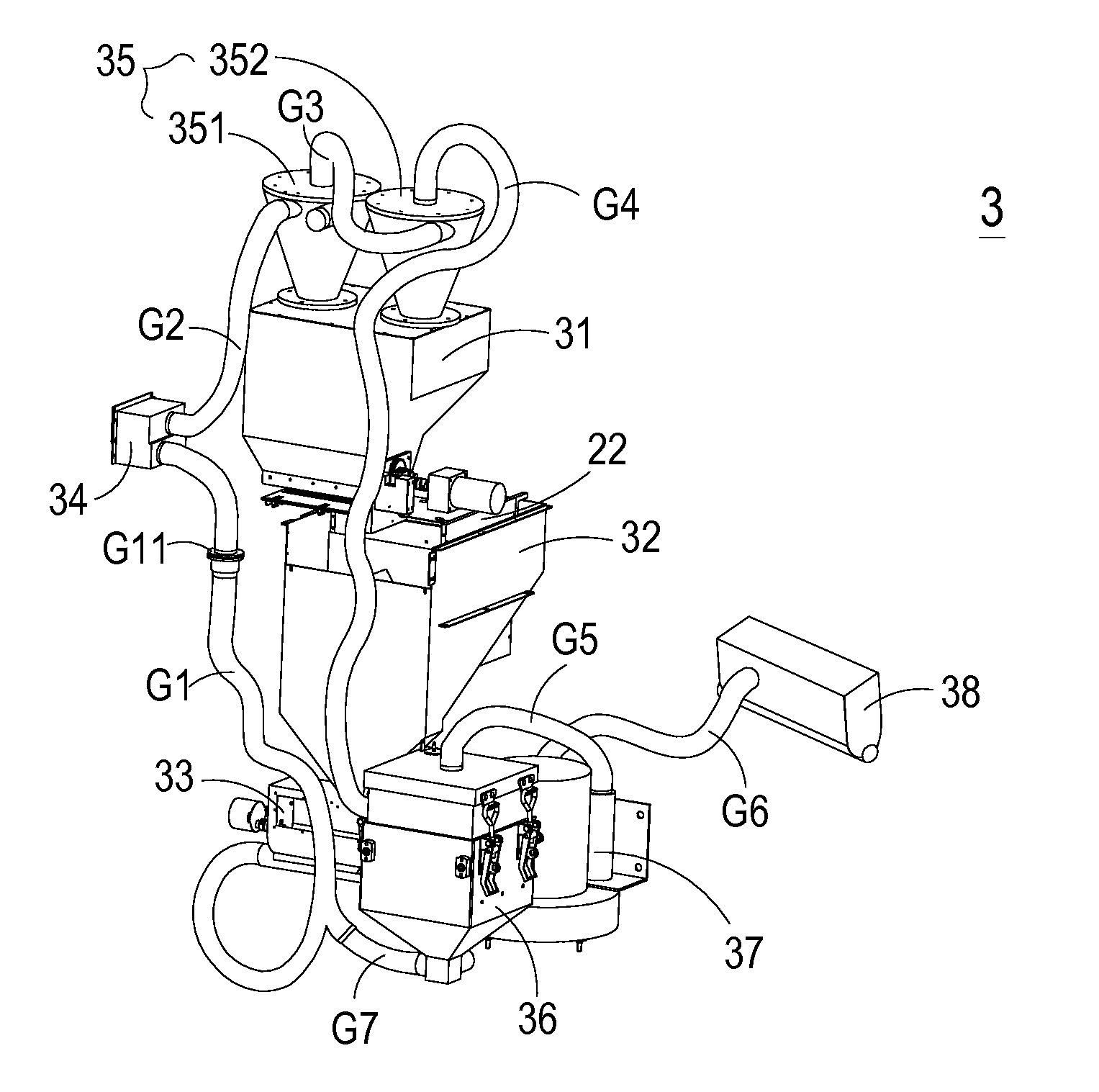
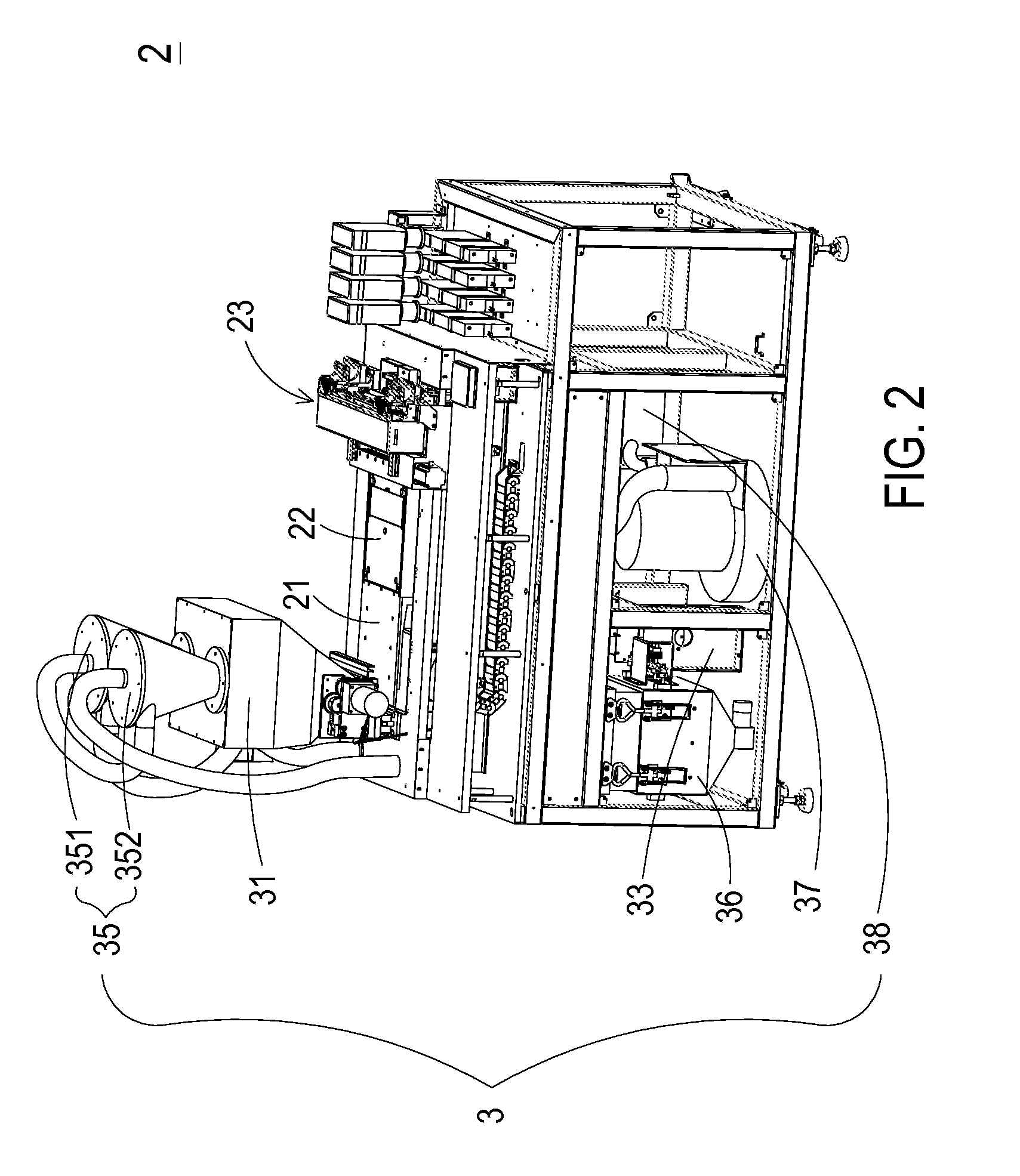
[0033]FIG. 2 is a schematic perspective view illustrating a three-dimensional object forming apparatus according to an embodiment of the present invention. FIG. 3 is a schematic perspective view illustrating a powder recycling system of the three-dimensional object forming apparatus according to the embodiment of the present invention. Please refer to FIGS. 2 and 3. The three-dimensional object forming apparatus 2 is used for producing a three-dimensional object (not shown). The three-dimensional object forming apparatus 2 comprises a construction platform 21, a construction chamber 22, a printing module 23 and a powder recycling...


PUM

PropertyMeasurementUnit
sizeaaaaaaaaaa
pressureaaaaaaaaaa
weightaaaaaaaaaa

Abstract

A powder recycling system includes a powder feeder, a remaining powder collector, a bridge breaker, a block powder filter, a cyclone separator, a particulate filter cleaner, an air pressure generation device and an electrostatic precipitator. The powder feeder provides a construction powder to a construction platform. The remaining powder collector for collects the remaining powder. The cyclone separator is used to separate the large-size powdery particles and the small-size powdery particles of the remaining powder from each other through a rotating gaseous stream. The large-size powdery particles fall down to the powder feeder due to gravity, and the small-size powdery particles of the remaining powder is removed from the rotating gaseous stream and transmitted to the particulate filter cleaner. After the small-size powdery particles of the remaining powder are filtered by the particulate filter cleaner, the suspended small-size powdery particles are transmitted to the electrostatic precipitator.

Description

FIELD OF THE INVENTION[0001]The present invention relates to a powder recycling system, and more particularly to a close-type powder recycling system for a three-dimensional object forming apparatus.BACKGROUND OF THE INVENTION[0002]As known, a rapid prototyping (RP) technology is developed from the concepts of forming a pyramid by stacking layers, and the main technical feature is to achieve fast formation. A complicated design can be transformed into a three-dimensional physical model automatically and fast without any cutting tools, molds and fixtures. Thus, the development cycle of new products and research and development cost are largely reduced to ensure the time to market for new products and the first-time-right ratio. Accordingly, a complete and convenient product design tool is provided between technicians and non-technicians (e.g. managers and users), and the product competitiveness and the quick reaction capability of enterprises in the market are improved obviously.[000...

Claims


Application Information

Patent Timeline
Patent Type & Authority Patents(United States)
IPC IPC(8): B07B9/02B03C3/017B07B4/00B29C67/00B33Y40/00B33Y10/00
CPCB29C67/0096B03C3/017B07B4/00B07B9/02B29C67/0088B33Y10/00B33Y40/00B01D36/00B07B9/00B29C64/357B65D88/68B29C64/393B29C64/35
Inventor CHEN, CHANG-CHIHCHEN, CHIH-KAISHI, KWO-YUANHUANG, CHI-FENG
Owner MICROJET TECH
Why Eureka
Try Eureka