Laser system and method for the treatment of body tissue

a laser system and body tissue technology, applied in the field of laser system for the treatment of body tissue, can solve the problems of difficult to achieve the effect of reducing or turning the laser intensity

Active Publication Date: 2017-04-04
FOTONA D O O
View PDF10 Cites 25 Cited by
  • Summary
  • Abstract
  • Description
  • Claims
  • Application Information

AI Technical Summary

Benefits of technology

[0019]Another important advantage of the invention is that the laser system can be electronically controlled to adjust the scanning pattern and / or laser energy depending on the position of the beam on the circumferential surface of the body cavity. For example, in gynecological treatments, the scanner can be programmed not to scan the beam over the urethra. Alternatively, the laser intensity can be reduced or turned off when the beam is being scanned over the urethra.
[0020]The treatment head is made out of a material which is optically transparent (i.e. substantially non-absorbing) at the laser wavelength used for treatment. “Substantially non-absorbing material” means a material with a laser beam transmission within the treatment head beam path length that is above 80%. Preferably, the treatment head base body is of a cylindrical shape. However, any other suitable 3D shape, such as a cube, cuboid, hexagonal prism or a cone, can be used, provided that the shape terminates in a conically shaped output surface.
[0021]An important advantage of the invention as compared to the aforementioned reflecting conical mirror approach is that due to the fact that the beam interacts with the conical output surface twice (firstly by total reflection and secondly by a subsequent refraction), the dispersion in the longitudinal direction is subtracted out, and the beam is spread out only in a transverse direction, with the spot on the treated tissue having an elliptical shape.
[0022]Any radial emerging direction of the emerging beam section having a radial direction component relative to the treatment head's longitudinal axis might be desirable within the scope of the present invention.
[0023]However, the following inventive considerations lead to further improvements: The half opening angle α must be equal to or smaller than the critical angle αcr, required for the total internal reflection to occur. This ensures that the incoming beam is totally reflected at first contact with the conical surface, and does not exit the treatment head in a substantially longitudinal direction. The condition for the total reflection can be mathematically calculated with equation 2 (Eq. 2):α<αcrit=90°−arcsin(n2 / n1)  (Eq. 2)
[0024]Here, n1 is the index of refraction of the treatment head's optical material and n2 is the index of refraction of the material surrounding the treatment head's conical ending. This material may be air, externally supplied liquids such as water or acid, or internally generated bodily fluids such as blood.

Problems solved by technology

Absorption and the following transformation of laser irradiation into heat result in a rapid phase change which, in turn, creates internal pressures, causing micro-fracturing and micro-explosive removal of the mineral phase of the hard tissues.
Nevertheless, drawbacks of hard tissue laser surgery such as a considerable amount of time needed, lack of depth control, and highly sophisticated handling requirements are still formidable.
For this reason, laser bone cutting is still assessed to be inferior to many conventional as well as other methods, such as piezoelectric osteotomy.
This preference however leaves unanswered the question of how to handle the aforementioned issues like e.g. residual smear layers on the inner circumferential body tissue surface of said hole.
The treatment results of the inner circumferential body tissue surface by mechanical means are unsatisfactory.
One drawback of this solution is that the treatment head must consist of mechanical means for holding the conical reflection mirror in the proper position, making the design and manufacture of such treatment head relatively difficult.
Another drawback of this solution is that the reflected beam gets spread out not only in the transverse direction, due to the circular shape of the treatment head, but also in the longitudinal direction due to the varying radius of the cone in the longitudinal direction.
However, it is unsatisfactory when high power densities are required to treat or modify the tissue.
For this reason, the conical fiber tip technique is unsuitable for treating larger diameter cavities, where the reduction in laser power density is most pronounced.
Another drawback of this solution is that the body tissue is being treated indiscriminately over the whole circumference of the cavity.
A third drawback of this solution is that the laser beam impacts also on the sharp apex of the conical surface.
It is technologically challenging, if not impossible, to manufacture a perfect apex.
In addition, at high laser intensities, and with continued use, it is this apex that becomes damaged first.
For this reason, the part of the beam which impinges on the apex becomes at least partially transmitted also in the forward (longitudinal) direction, possibly damaging the tissue at the bottom of the treated cavity.

Method used


Image

  • Laser system and method for the treatment of body tissue
  • Laser system and method for the treatment of body tissue
  • Laser system and method for the treatment of body tissue

Examples


Embodiment Construction

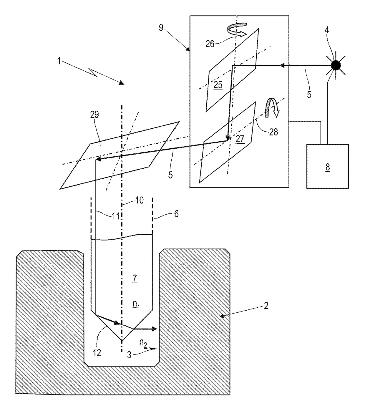
[0049]FIG. 1 shows in a schematic cross sectional view a cavity in body tissue 2, wherein said cavity forms an inner circumferential tissue surface 3. For the treatment of the body tissue 2 on the inner circumferential tissue surface 3 an inventive laser system 1 and related inventive operation method is provided. The inventive laser system 1 is depicted in a schematic block diagram.

[0050]The laser system 1 comprises a laser source 4 for the generation of laser beam 5, a hand piece 6 with a treatment head 7, a control device 8, and a scanner 9. The scanner 9 comprises two mirrors 24, 27, which are rotationally movable about two perpendicular axes 26, 28. The rotational movement of both mirrors 25, 27 is controlled by the control device 8. Alternatively, the scanner 9 may comprise of only one mirror, 25 or 27, which is rotationally movable about two perpendicular axes. The control device 8 further controls the operation of the laser source 4 in terms of intensity and pulse sequences....


PUM


Abstract

A laser system for body tissue treatment has laser source, control device, scanner, and handpiece with treatment head transparent to the laser beam. An incoming laser beam section enters the treatment head longitudinally. The treatment head has a conical output surface with a minimum and a maximum surface radius and a half opening angle for total reflection of the incoming beam section. The reflected beam section is refracted radially into an emerging beam section away from the treatment head through the output surface. The incoming beam section has at the output surface a mean diameter that is ≦a difference of maximum surface radius and minimum scanning radius. A conical scanning surface as a part of the conical output surface extends from the minimum scanning radius to the maximum surface radius. The control device controls the scanner for scanning the conical scanning surface with the incoming beam section.

Description

BACKGROUND OF THE INVENTION[0001]The present invention relates to a laser system for the treatment of body tissue on an inner circumferential tissue surface and to a related method.[0002]Various laser wavelengths, which are highly absorbed in water, such as Er:YAG (2.94 μm wavelength), Er,Cr:YSGG (2.73 μm wavelength), CO2 (8-11 μm wavelength) have been advocated as possible and promising alternatives to conventional instruments in different medical and surgical disciplines. Due to their characteristic absorption maxima in water which is an important constituent of body tissues, they are considered to be suitable not only for the treatment of soft tissue structures but also for ablating mineralized hard tissues. Contact-free laser ablation offers the opportunity of cutting bone and other hard tissue without friction that may cause additional thermal and mechanical trauma. Consequently, the risk of cell death and delayed healing may be minimized. Furthermore, in contrast to convention...

Claims


Application Information

Patent Timeline
Patent Type & Authority Patents(United States)
IPC IPC(8): A61B18/20A61B18/22A61N5/06
CPCA61B18/20A61B18/22A61B2018/2085A61B2018/2095A61B2018/2277A61N5/0603A61N2005/0644A61N2005/0659A61B2018/20351A61B2018/20359A61B2018/2244
Inventor KAZIC, MARKOLUKAC, MATJAZ
Owner FOTONA D O O
Why Eureka
Try Eureka