
Compression ring and its production method

a compression ring and production method technology, applied in the direction of heat treatment equipment, braking systems, furnaces, etc., can solve the problems of deteriorating thermal sag resistance and the inability to use compression rings in high-thermal-load environments, and achieve excellent thermal conductivity and thermal sag resistance, good price competitiveness

Active Publication Date: 2017-04-11
TOKUSEN IND CO LTD +1
View PDF33 Cites 0 Cited by
  • Summary
  • Abstract
  • Description
  • Claims
  • Application Information

AI Technical Summary

Benefits of technology

[0006]An object of the present invention is to provide a compression ring having excellent thermal conductivity and thermal sag resistance as well as good price competitiveness, which can be used in a high-thermal-load environment in high-compression-ratio engines, and a method for producing such a compression ring.SUMMARY OF THE INVENTION
[0009]However, the thermal sag resistance is actually deteriorated as the amounts of alloying elements decrease, making impossible use for compression rings in a high-thermal-load environment. Steel is generally more inexpensive as the amounts of alloying elements are smaller. Also, from the economic point of view, steel used in a large amount, namely, mass-produced like materials defined by JIS (Japanese Industrial Standards) is inexpensive. Accordingly, the present invention basically uses a JIS-defined material containing small amounts of alloying elements, with its microscopic structure controlled to have excellent thermal sag resistance even at a high temperature of 300° C. As a result of intensive research, the inventors have found that specifically using steel identified by the material number of SUP10 in JIS G 4801, when a piston ring wire is annealed before an oil-tempering treatment to precipitate spheroidal cementite, with the oil-tempering treatment conditions optimized, a proper amount of spheroidal cementite is dispersed in a tempered martensite matrix, suppressing the movement of dislocation and creep even at 300° C., and improving the thermal sag resistance.

Problems solved by technology

However, the thermal sag resistance is actually deteriorated as the amounts of alloying elements decrease, making impossible use for compression rings in a high-thermal-load environment.

Method used


Image

  • Compression ring and its production method
  • Compression ring and its production method
  • Compression ring and its production method

Examples


examples 1-3

E1 to E3

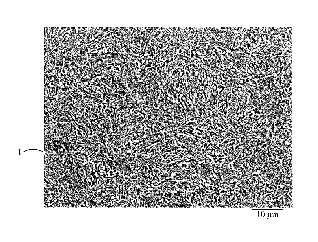
[0024]Each wire of SUP10 steel rolled to 8 mm in diameter was formed into a rectangular cross-sectioned wire of 1.0 mm in thickness and 2.3 mm in width, by conducting an annealing step at 700° C. for 60 minutes in place of the second patenting treatment, in a wire-forming process comprising heating at 900° C., patenting at 600° C., washing with acid, wire drawing, heating at 900° C., patenting at 600° C., washing with acid, wire drawing and oil-tempering. The oil-tempering treatment comprised a quenching step in an oil at 60° C. after heating at 930° C. for 45 seconds, and a tempering step at 470° C. for 60 seconds. FIG. 1 shows the structure of the wire observed by a scanning electron microscope, in which white fine spheroidal cementite (1) was dispersed in a tempered martensite. Image analysis on an enlarged photomicrograph of this structure revealed that the spheroidal cementite had an average particle size of 0.8 μm and an area ratio of 2.4%.

examples 4-5

E4 to E5

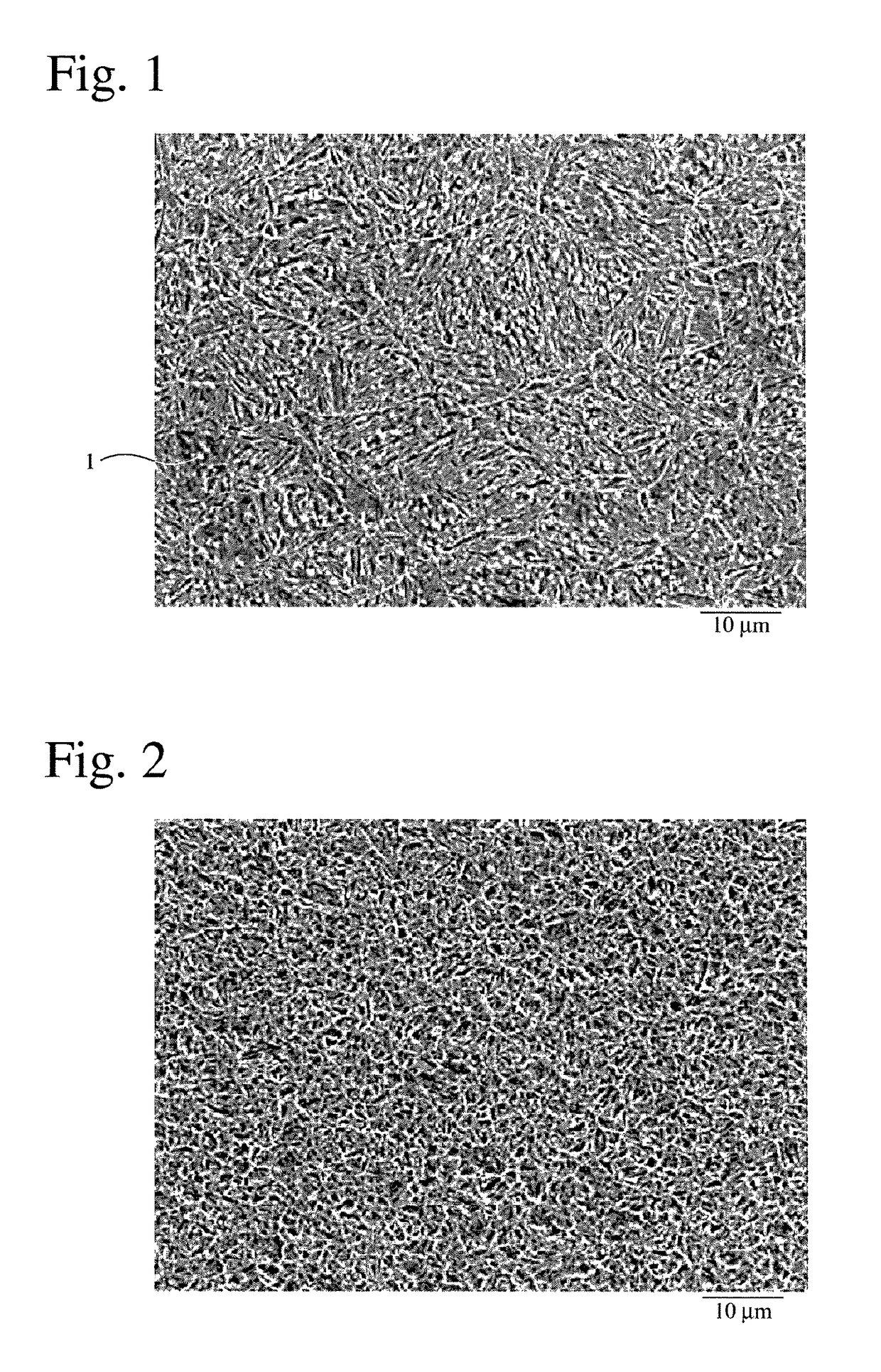
[0025]Each rectangular cross-sectioned wire of 1.0 mm in thickness and 2.3 mm in width was produced from the SUP 10 steel by conducting annealing at 700° C. in place of the second patenting treatment as in Examples 1-3. To control the spheroidal cementite dispersed in a tempered martensite matrix, the temperature of heating before quenching in the oil-tempering treatment was 980° C. in Example 4, and 820° C. in Example 5. Image analysis conducted in the same manner as in Example 1 on scanning electron photomicrographs of the wire structures revealed that the spheroidal cementites in Examples 4 and 5 had average particle sizes of 0.4 μm and 1.2 μm, respectively, and area ratios of 0.3% and 5.3%, respectively.

[0026]Each rectangular cross-sectioned wire of 1.0 mm in thickness and 2.3 mm in width in Examples 1-5 was formed into a compression ring having a nominal diameter of 73 mm, which was subject to a coating treatment shown in Table 2. Namely, a peripheral surface of the com...


PUM

PropertyMeasurementUnit
thermal conductivityaaaaaaaaaa
temperatureaaaaaaaaaa

Abstract

To provide a price-competitive compression ring having excellent thermal conductivity and thermal sag resistance, which can be used in a high-thermal-load environment of high-compression-ratio engines, steel identified by the material number of SUP10 in JIS G 4801, which contains small amounts of alloying elements, is used, and a piston ring wire is annealed before an oil-tempering treatment such that spheroidal cementite having an average particle size of 0.1-1.5 μm is dispersed in a tempered martensite matrix, thereby suppressing the movement of dislocation and creep even at 300° C., and improving thermal sag resistance.

Description

FIELD OF THE INVENTION[0001]The present invention relates to a piston ring for automobile engines, particularly to a compression ring used in a high-thermal-load environment in high-compression-ratio engines, and its production method.BACKGROUND OF THE INVENTION[0002]For environmental protection, automobile engines are recently designed to have improved fuel efficiency, low emission and high power, so that engines tend to have high compression ratios and high load. However, higher compression ratios generally elevate combustion chamber temperatures, so that knocking easily occurs. A usual measure against knocking is the delaying of ignition timing (spark advance), but it makes it impossible to keep high thermal efficiency. Accordingly, investigation is conducted to lower the temperature of combustion chamber walls. To lower the temperature of combustion chamber walls, it is effective to lower the temperature of piston crown surfaces. To this end, it is most effective to dissipate th...

Claims


Application Information

Patent Timeline
Patent Type & Authority Patents(United States)
IPC IPC(8): F02F5/00C21D9/40C22C38/02C22C38/04C22C38/24F16J9/26
CPCF02F5/00C21D9/40C22C38/02C22C38/04C22C38/24F16J9/26
Inventor SHIMA, YUJITAKAHASHI, JUNYAKAMON, RYOUICHI
Owner TOKUSEN IND CO LTD
Learn More