Moisture sensor for monitoring an access to a patient and method of producing the moisture sensor

a moisture sensor and patient technology, applied in the field of moisture sensors, can solve the problems of changing the resistance between the conductor paths, the problem of terminating resistors to the substrate material, and the difficulty of connecting up external terminating resistors, etc., and achieve the effect of producing moisture sensors inexpensively in large numbers and inexpensively produced

Active Publication Date: 2017-04-25
FRESENIUS MEDICAL CARE DEUTSCHLAND GMBH
View PDF24 Cites 30 Cited by
  • Summary
  • Abstract
  • Description
  • Claims
  • Application Information

AI Technical Summary

Benefits of technology

[0013]An object underlying the present invention is to provide a moisture sensor for monitoring a patient access which can be inexpensively produced in large numbers. It is also an object of the present invention to specify a method of producing the moisture sensor inexpensively in large numbers.
[0016]The moisture sensor according to the present invention has the advantage that an external terminating resistor is not required. This simplifies the connecting up of the moisture sensor. The moisture sensor according to the present invention can be easily produced in large numbers complete with the terminating resistor by applying the conductive film as a web of film during the production process. The web of film having been applied, the moisture sensors can be separated out, complete with the terminating resistor, by cutting, punching or stamping the moisture sensors, complete with the terminating resistor, out of the web of material they form together.
[0020]The electrically conductive structure may take different forms. In a preferred exemplary embodiment, the electrically conductive structure has a first conductor path and a second conductor path, with the electrical contacting portions for the connection of the terminating resistor being formed at one end of the first conductor path and one end of the second conductor path. The other end of the first conductor path and the other end of the second conductor path preferably take the form of electrical connecting contacts for an electrical connector for connecting the moisture sensor to the sensing arrangement. The electrical contacting portions for the terminating resistor are preferably arranged on one side of the substrate material and the electrical connecting contacts for the connector are preferably arranged on the other side thereof. This makes it possible for the terminating resistor to be produced by applying the electrically conductive film to the side of the moisture sensor which has the contacting portions.
[0021]The substrate material of the moisture sensor preferably takes the form of a planar material, with the electrical contacting portions and the electrical connecting contacts being arranged on a tongue belonging to the planar material. The tongue on the one hand allows the connector to be connected easily and on the other hand allows the electrically conductive film to be applied because the tongue is physically separated from the electrically conductive structure.
[0022]A particularly preferred exemplary embodiment makes provision for a substrate material of non-conductive warp filaments and non-conductive weft filaments and conductive warp filaments and conductive weft filaments, the electrically conductive structure being formed by conductive warp filaments and / or weft filaments. The advantages of the moisture sensor according to the present invention are particularly apparent in this exemplary embodiment because the web of conductive film can easily be connected to the web of woven material. The electrically conductive film may be any film which has a suitable resistance. What are suitable as electrically conductive films are for example the known carbon films or polymer films.

Problems solved by technology

Wetting of the substrate material by a liquid results in a change in the resistance between the conductor paths.
An electrically conductive structure which comprises two conductor paths open at the ends which are arranged at a distance from one another is a disadvantage in that the sensing arrangement is not able to detect either any damage to the conductor paths or a misconnection of the moisture sensor, because a break in a conductor path or the connecting line or the making of a faulty contact at the connection does not cause a change in resistance.
The application of the terminating resistor to the substrate material is found to be problem in production.
However, it is costly and complicated to connect up external terminating resistors.
Although it is fundamentally possible for the terminating resistor to be applied by printing even in the case of a moisture sensor made of a textile material, it is found to be a disadvantage because of the additional steps in the procedure which are called for by the printing process.

Method used


Image

  • Moisture sensor for monitoring an access to a patient and method of producing the moisture sensor
  • Moisture sensor for monitoring an access to a patient and method of producing the moisture sensor
  • Moisture sensor for monitoring an access to a patient and method of producing the moisture sensor

Examples


Embodiment Construction

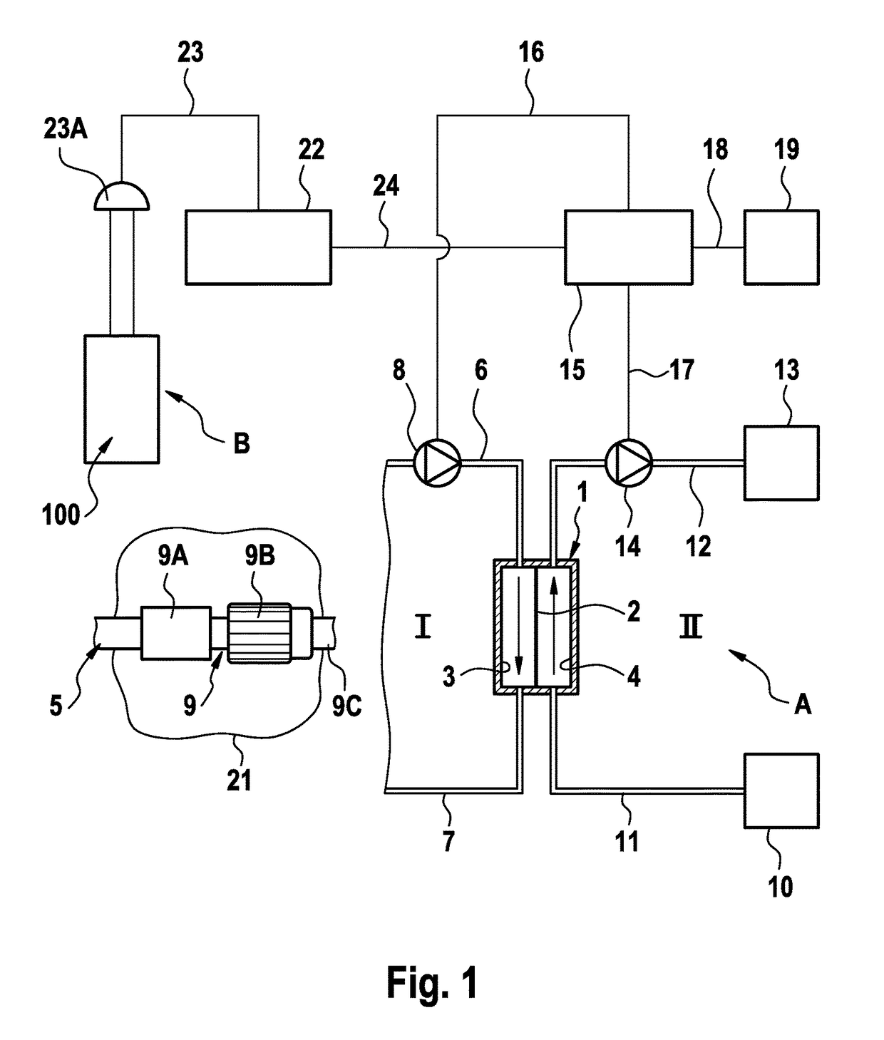
[0039]FIG. 1 shows the principal components of a blood treatment apparatus, and in particular a haemodialysis apparatus A for acute dialysis, which has an arrangement B for monitoring a vascular access and in particular a vascular access which has a central venous catheter. The monitoring arrangement B is part of the haemodialysis apparatus A in the present exemplary embodiment. The dialysis apparatus will first be described with reference to FIG. 1.

[0040]The haemodialysis apparatus A has a dialyser 1 which is divided into a blood chamber 3 and a dialysis-fluid chamber 4 by a semi-permeable membrane 2. The vascular access to the patient is obtained by means of a central venous catheter 5 which is connected to the patient's neck. The central venous catheter 5 is part of the extra-corporeal blood circuit I, which is merely indicated and which includes the blood chamber 3 of the dialyser 1 and comprises flexible lines 6, 7. A blood pump 8 is provided to pump the blood in the extra-corp...


PUM

PropertyMeasurementUnit
flexibleaaaaaaaaaa
electrically conductiveaaaaaaaaaa
distanceaaaaaaaaaa

Abstract

A moisture sensor for monitoring an access to a patient for a system by which, via a flexible line, a liquid is fed to and / or out from a patient, for monitoring the vascular access in extra-corporeal blood treatment or for monitoring a central venous catheter for acute dialysis, and a method of producing a moisture sensor are described. The moisture sensor has a substrate material with an electrically conductive structure having conductor paths arranged at a distance from one another and connected together across a terminating resistor. The terminating resistor is an electrically conductive film which is applied in a section of the substrate material on which are formed electrical contacting regions for connecting the terminating resistor to the conductor paths, such that an external terminating resistor is not required and the moisture sensor can be produced easily in large numbers complete with the terminating resistor.

Description

CROSS REFERENCE TO RELATED APPLICATIONS[0001]The present application claims priority to U.S. Provisional Patent Application Ser. No. 61 / 669,162, filed on Jul. 9, 2012, and Application No. DE 10 2012 013 471.1, filed in the Federal Republic of Germany on Jul. 9, 2012, each of which is expressly incorporated herein in its entirety by reference thereto.FIELD OF INVENTION[0002]The present invention relates to a moisture sensor for monitoring an access to a patient for a system by which, via a flexible line, a liquid is fed to a patient and / or a liquid is fed out from the patient, and in particular for monitoring the vascular access in extra-corporeal blood treatment. As well as this, the present invention also relates to a method of producing a moisture sensor for monitoring an access to a patient.BACKGROUND INFORMATION[0003]In the field of medical engineering, there are various known systems with which, via a flexible line, liquids can be withdrawn from patients or liquids can be fed t...

Claims


Application Information

Patent Timeline
Patent Type & Authority Patents(United States)
IPC IPC(8): A61M5/50G01M3/16A61M1/36A61B5/02A61M5/158G01N27/04
CPCA61M5/5086A61B5/02042A61M1/3656G01M3/16A61M2005/1588A61M2205/15A61M2205/3317G01N27/048Y10T29/49117
Inventor WUEPPER, ANDREAS
Owner FRESENIUS MEDICAL CARE DEUTSCHLAND GMBH
Why Eureka
Try Eureka